Mechanical Assembly For A Power Tool

a technology of mechanical assembly and power tools, applied in the direction of gearing control, sleeve/socket joint, toothed gearing, etc., can solve the problems of unsuitable torque that the torque control means allows to be applied, add considerably to the length of the power drill between the drive motor, and the overall length of the power drill, etc., to facilitate gripping or releasing the working element, facilitate the driving of the working element, and facilitate the effect of reducing the length

Inactive Publication Date: 2010-08-12
DEMAIN TECH
View PDF12 Cites 47 Cited by
  • Summary
  • Abstract
  • Description
  • Claims
  • Application Information

AI Technical Summary

Benefits of technology

[0014]The present invention is advantageous over existing mechanical assemblies for power tools in that it provides first and second members that each include engagement portions that are inclined relative to the axes of the members. Thus, the invention enables the overall length of the members in the direction of the axes to be reduced while still providing engagement portions of a length and / or surface area sufficient to provide secure engagement therebetween. This facilitates providing a power tool that is compact, particularly in the direction of the axes of the first and second members, while still providing secure engagement therebetween. Furthermore, the invention may achieve the above outcomes without requiring a relatively large amount of force acting on either the first or the second member in the direction of either one of the axes of the first and second members to urge the either the first or the second member into secure engagement with the other one of the first and second members. For example, the relatively large length and / or surface area of the engagement portions resulting from their inclined configuration in the above arrangement does not require an excessively large force to act on either the first or the second member to ensure that the engaging portions do not slip or otherwise come out of engagement.
[0067]Thus, the switch facilitates adjustment of the driven member to grip or release a working element and to drive rotation of the working element at differing speeds of rotation relative to the speed of rotation of the power drive. Also, the above power tool arrangement does not require a user to adjust the torque setting of either of the torque control means to utilise differing torque settings in the drive mode and the adjustment mode because the switch enables operation of either one of the two torque control means each with their own torque setting in the drive mode and the adjustment mode respectively.

Problems solved by technology

However, in such power drills the mechanical assembly is typically located between the drive motor and the chuck and this can add considerably to the length of the power drill between the drive motor and the chuck and to the length of the power drill overall.
This is a particular disadvantage when power tools incorporating a mechanical assembly such as the one described above are being marketing in competition with more compact power drills that do not incorporate such a mechanical assembly, such as power drills that do not include adjustment and drive modes.
However, the amount of torque that the torque control means allows to be applied may not be an appropriate amount of torque to prevent damage to the power tool or the working element when the power dill is in the adjustment mode for clamping or releasing a working element.
In power tools in which the torque control means involves manually rotating a knob through a range of graduated torque settings or some other equivalent manual adjustment means, it is not convenient to have to adjust the torque control means whenever the user wishes to operate the power tool in the adjustment mode and the drive mode.

Method used


Image

  • Mechanical Assembly For A Power Tool
  • Mechanical Assembly For A Power Tool
  • Mechanical Assembly For A Power Tool

Examples


Embodiment Construction

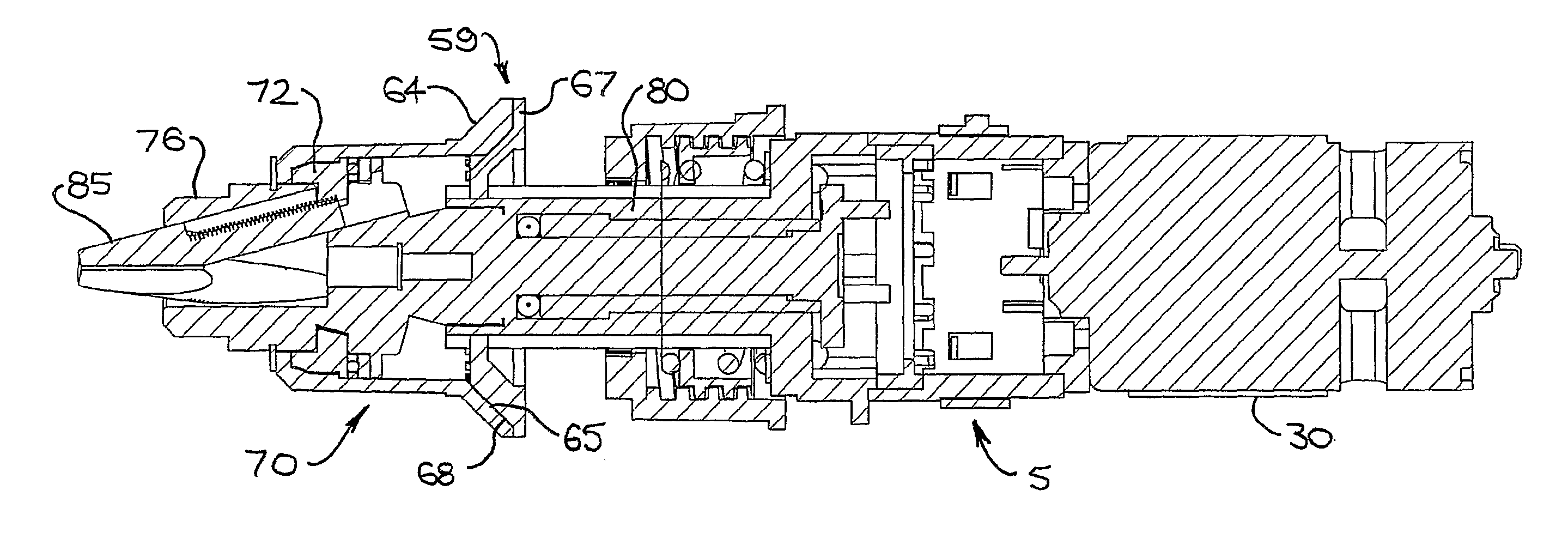
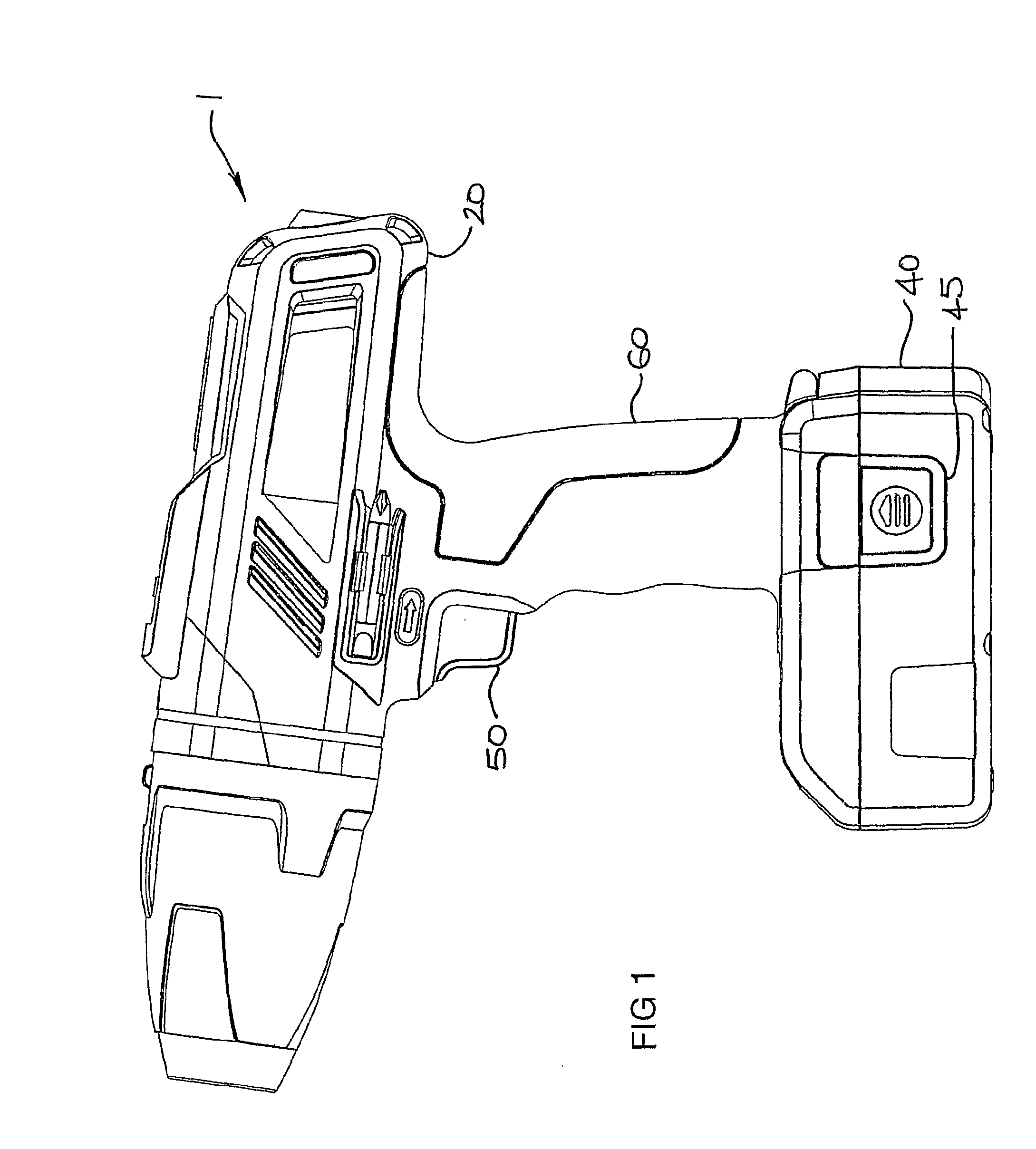
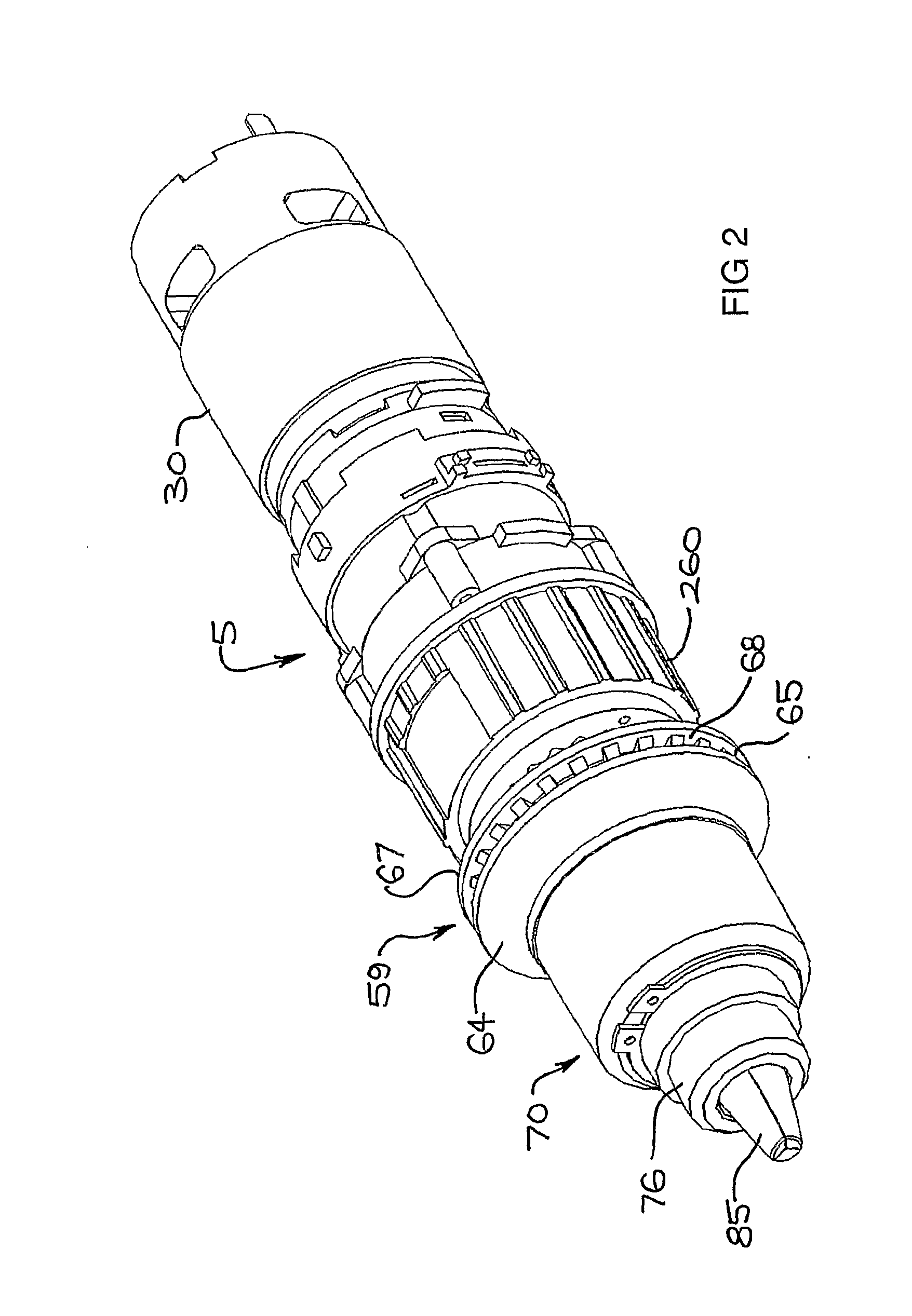
[0100]FIGS. 1 to 17 illustrate preferred embodiments of the invention in the form of a drive train 5 incorporated into a hand held power drill 1. However, the invention is applicable to other power tools that may or may not be hand held or portable. The power drill 1 includes a power drill body 20 integrally formed with a pistol grip handle 60 for gripping the power drill 1. While the arrangement of the handle 60 illustrated in the drawings is in the form of a pistol grip that is moulded to the shape of a user's hand, that is, the grip includes depressions to receive the fingers of a user, it is to be appreciated that other shapes and configurations of the handle 60 may be employed.

[0101]The body 20 of the power drill 1 has a generally cylindrical shape and encases components of the power drill 1 such as a motor 30. Incorporated into the handle 60 adjacent to the body 20 of the power drill 1 is a trigger 50 for actuating a switch (not shown) within the handle 60. Also incorporated i...


PUM

PropertyMeasurementUnit
mechanical assemblyaaaaaaaaaa
movementaaaaaaaaaa
torqueaaaaaaaaaa

Abstract

The invention relates to a mechanical assembly for a power tool, and a power tool incorporating the mechanical assembly. The mechanical assembly includes a first member having a first axis and a first engagement portion inclined relative to the first axis and a second member having a second axis and a second engagement portion inclined relative to the second axis. The first and second engagement portions engage each other by movement of the first and second members relative to each other in the direction of at least one of the axes. The power tool includes a power tool body and a rotatable driven member being operable for releasably gripping a working element, the driven member having a drive mode in which rotation of the driven member drives the working element relative to the power tool body and an adjustment mode in which rotation of the driven member causes the driven member to either grip the working element or release the working element or both. The power tool also includes means for adjusting the driven member between the modes which includes the mechanical assembly wherein the first and second engagement portions engage each other by movement of the first and second members relative to each other in the direction of at least one of the axes and wherein engagement between the first and second engagement portions adjusts the driven member to the adjustment mode and disengagement between the first and second engagement portions adjusts the driven member to the drive mode. The power tool may also include a first torque control means that is operable for controlling the amount of torque applied to the driven member by the power drive when in the drive mode and a second torque control means that is operable for controlling the amount of torque applied to the driven member by the power drive when in the adjustment mode. The power tool may further include a gearbox with one or more speeds and a switch with two or more positions that is operable for selecting the modes, the gear speeds and the first and second torque control means.

Description

FIELD OF THE INVENTION[0001]This invention relates to power tools. The invention is suitable for use with power tools that use a drill bit, a saw blade, a cutting wheel or any other element used to cut shape or otherwise treat a workpiece. The invention is particularly suitable for use with power tools incorporating a driven member that is operable for releasably gripping a working element.[0002]A power drill is one form of power tool with which the invention is applicable. For the sake of convenience the invention is described below in the context of power drills, but it is to be understood that the invention may have broader application.BACKGROUND OF THE INVENTION[0003]Most existing power drills have a three jaw chuck for gripping a drill bit. The chuck jaws are adjustable to suit drill bits of various sizes. In most cases such adjustment is carried out by use of a key or by manually twisting the outer sleeve of the chuck or alternatively the user grips the outer sleeve and power ...

Claims


Application Information

Patent Timeline
Patent Type & Authority Applications(United States)
IPC IPC(8): B23B47/14F16H1/14B25F5/00
CPCB23B31/1238Y10T74/2014B25F5/001B27B5/32B23B31/24B23B2231/38F16D11/14Y10T279/17615Y10T279/17632Y10T74/19688Y10T74/19614Y10T279/17Y10T74/19242Y10T279/17623Y10T408/94B23B45/008
Inventor SCRIMSHAW, DAVID LEIGHVAN DER LINDE, BENJAMIN LUKECONNOR, PAUL FRANCISMILLER, PAUL
Owner DEMAIN TECH
Why Eureka
Try Eureka