Tapered coupling structure and rotating machine

a coupling structure and rotating machine technology, applied in the direction of couplings, mechanical actuated clutches, interengaging clutches, etc., can solve the problems of difficult to reuse the hub, thermal deformation of the hub, and difficult to heat the hub. , to achieve the effect of high surface pressur

Active Publication Date: 2010-08-12
MITSUBISHI HEAVY INDUSTIES COMPRESSOR CORP
View PDF6 Cites 59 Cited by
  • Summary
  • Abstract
  • Description
  • Claims
  • Application Information

AI Technical Summary

Benefits of technology

[0024]The tapered coupling structure in accordance with the present invention can feed oil preferentially to a region having a high surface pressure because the first oil groove for feeding the oil to the coupling surfaces of the taper part and the hub is provided in the first region corresponding to the high-rigidity part in the axial direction. As a result, there can be provided the tapered coupling structure in which the tapered shaft can be coupled to and decoupled from the hub without the use of an O-ring.

Problems solved by technology

However, the work for heating the hub is not easy to perform in the case where the hub is large.
Also, the heating of hub may produce thermal deformation of the hub.
In this case, it is difficult to reuse the hub as it is as a rotating body.
As described in Registered Utility Model No. 3054261, the coupling structure in which coupling and decoupling are performed by hydraulic pressure has a problem in that oil scatters from the oil groove, and contaminates the surroundings.
However, with regard to the coupling structure, a problem described below has been brought forward.
The reason for this is that it is supposed that if the O-ring is broken during the use of the coupling structure, decoupling of the tapered shaft from the hub may become difficult to do.
In the coupling structure without the use of O-rings, the fed oil is liable to leak from the end part of the structure, so that a hydraulic pressure necessary for coupling or decoupling is difficult to obtain.
If coupling or decoupling is performed forcedly in this state, scratches occur on the outer peripheral surface of the tapered shaft and the inner peripheral surface of the hub.

Method used


Image

  • Tapered coupling structure and rotating machine
  • Tapered coupling structure and rotating machine
  • Tapered coupling structure and rotating machine

Examples


first embodiment

[0032]The present invention will now be described in detail based on a first embodiment shown in the accompanying drawing.

[0033]FIGS. 3A and 3B are sectional views of a coupling structure 10 in accordance with the first embodiment, FIG. 3A being a sectional view taken along the line 3a-3a of FIG. 3B, and FIG. 3B being a sectional view taken along the line 3b-3b of FIG. 3A.

[0034]The coupling structure 10 is made up of a tapered shaft 20 and a hub 30 coupled to the tapered shaft 20. The tapered shaft 20 constitutes, for example, the output shaft of a steam turbine, not shown. The hub 30 is connected to, for example, the input shaft of a compressor, not shown, and functions as an element for transmitting the output of the steam turbine to the compressor.

[0035]The tapered shaft 20 includes a taper part 21 the diameter of which decreases toward the tip end. In the present invention, the tip end side of the tapered shaft 20 is defined as the front, and the opposite side thereto as the rea...

second embodiment

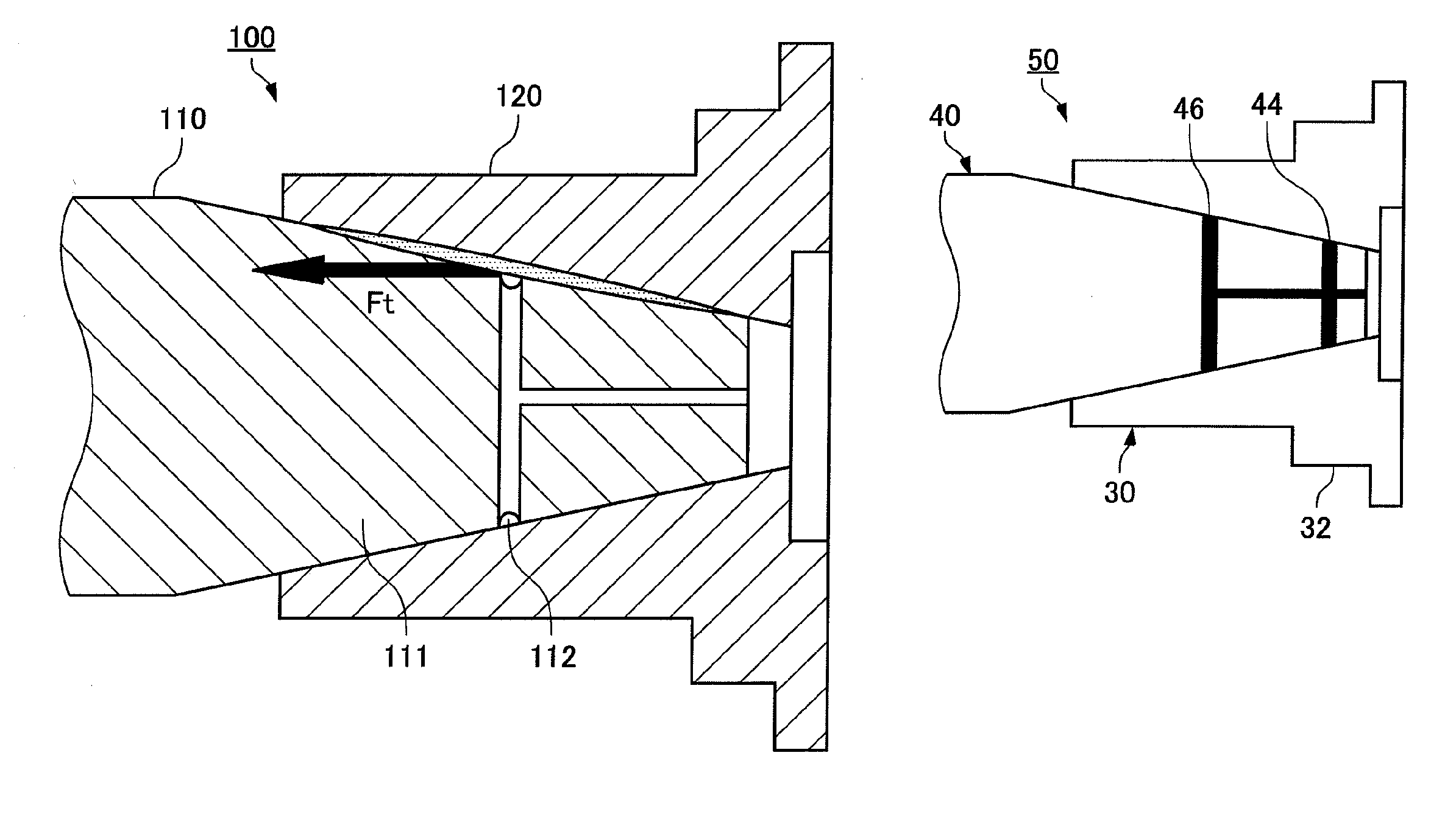
[0043]FIG. 4 is a sectional view of a coupling structure 50 in accordance with a second embodiment.

[0044]The coupling structure 50 comprises a tapered shaft 40 and the hub 30 coupled to the tapered shaft 40. The hub 30 is the same as that of the first embodiment, and therefore the explanation thereof is omitted.

[0045]The tapered shaft 40 includes a taper part 41, and an axial oil passage 42 is formed along the axial direction of the tapered shaft 40 from the front end surface of the taper part 41. Also, in the radial direction of the taper part 41, a first radial oil passage 43 and a second radial oil passage 45, which is provided at a predetermined interval from the first radial oil passage 43, are formed. The first radial oil passage 43 communicates with the axial oil passage 42, and both ends thereof are open to the outer peripheral surface of the taper part 41. The second radial oil passage 45 communicates with the terminal end of the axial oil passage 42, and both ends thereof ...

third embodiment

[0050]FIGS. 5A, 5B and 5C are sectional views of a coupling structure 70 in accordance with the third embodiment, FIG. 5A being a sectional view taken along the line 5a-5a of FIG. 5B, FIG. 5B being a sectional view taken along the line 5b-5b of FIG. 5A, and FIG. 5C being a sectional view taken along the line 5c-5c of FIG. 5A.

[0051]The coupling structure 70 comprises a tapered shaft 60 and the hub 30 coupled to the tapered shaft 60. The hub 30 is the same as that of the first embodiment, and therefore the explanation thereof is omitted.

[0052]The tapered shaft 60 comprises a taper part 61, and an axial oil passage 62 is formed along the axial direction of the tapered shaft 60 from the front end surface of the taper part 61. Also, in the radial direction of the taper part 61, a radial oil passage 63 is formed. The radial oil passage 63 communicates with the terminal end of the axial oil passage 62, and both ends thereof are open to the outer peripheral surface of the taper part 61. The...


PUM


Abstract

There is provided a tapered coupling structure in which a tapered shaft can be coupled to and decoupled from a hub without the use of an O-ring. In a tapered coupling structure 10 in which a tapered shaft 20 and a hub 30 are coupled to each other, the tapered shaft 20 is provided with a taper part 21 on the side of being coupled to the hub 30, and the hub 30 is provided with a high-rigidity part 32 having a thickness in the radial direction larger than that of other regions and having a high rigidity in the radial direction. An oil groove 24 formed in the outer peripheral surface of the taper part 21 to feed oil to the coupling surfaces of the taper part 21 and the hub 3 is provided in a region corresponding to the high-rigidity part 32 in the axial direction.

Description

BACKGROUND OF THE INVENTION[0001]1. Field of the Invention[0002]The present invention relates to a tapered coupling structure in which a shaft provided with a taper-shaped outer periphery and a hub provided with a taper-shaped inner periphery are coupled to each other.[0003]2. Description of the Related Art[0004]As a machine element for transmitting the output of a driver to driven equipment, a coupling has been known. Among various types of couplings, there has been known a coupling in which an output shaft of driver provided with a taper-shaped outer periphery in the shaft end portion thereof (hereinafter, referred to as a tapered shaft) and a hub into which the shaft end portion is inserted and which has a hollow part provided with a taper-shaped inner periphery are coupled to each other. This coupling structure is used to transmit high output, for example, to transmit the output of a steam turbine to a compressor, or to transmit engine power to a propeller shaft. In some cases, ...

Claims


Application Information

Patent Timeline
Patent Type & Authority Applications(United States)
IPC IPC(8): F16D11/04
CPCF16D1/092Y10T403/1633F16D2001/0906
Inventor YAGI, KATSUKITERADO, HIROKIYANAGISAWA, EIICHISHINOHARA, HITOSHI
Owner MITSUBISHI HEAVY INDUSTIES COMPRESSOR CORP
Why Eureka
Try Eureka