Directable Light

a directable light and light technology, applied in the field of lighting apparatuses, can solve the problems of unsuitable application outside the field of specialist spotlight tracking, unsuitable for remote movement, complex and expensive apparatus, etc., and achieve the effect of simple and cheapness, and easy processing of beam images

Inactive Publication Date: 2010-08-12
WESTAWAY ADRIAN LUCIEN REGINALD
View PDF3 Cites 32 Cited by
  • Summary
  • Abstract
  • Description
  • Claims
  • Application Information

AI Technical Summary

Benefits of technology

[0012]Broadly stated, the present invention directs a light beam and takes an image from radiation reflected by the light beam hitting an object, e.g. a wall. Changes in the image caused by movement of an object (which term includes for the purposes of this specification, a person and a shadow) in the beam is then analysed and the characteristics of the movement, e.g. speed, direction and / or acceleration of movement, is used to move the light beam in accordance with a preset algorithm. Although it is possible to use the invention to track the movements of an object, e.g. an actor or lecturer on a stage, so that the light beam is directed at them despite the fact that they are moving, the primary application of the present invention is to alter the direction of a light beam so that the invention can be used to “push” or “pull” the light beam in a different direction, which is not only useful when wanting to move the beam to illuminate a different target, but is also fun to do and so the present application has application as a plaything. This allows the present invention to provide a simpler and cheaper device that does not require the use of special markers or shape recognition to move the beam.
[0013]The image is captured by a radiation and movement sensor, which can fit on a microchip so that it can be made cheaply enough to be affordable in a domestic setting, e.g. for moving the beam direction in a light in a kitchen illuminating a work surface or altering the angle on a desk light.
[0017]For example, using either or both of these methods, the sensor could output a signal that is primarily dependent on the infrared radiation received and may be substantially insensitive to visible radiation. If the lamp used to produce the beam produces a substantial amount of infrared radiation, changes in the shape of the beam can be detected without the interference of visible light from other sources within the sensor's view.
[0018]The sensor can, for simplicity and cheapness, be in a fixed position relative to the light so that it surveys an area that is substantially larger than the size of the beam, which makes the processing of the beam image easier.
[0027]A lock may be provided that, when operational, prevents the beam being moved in accordance with movement in the image of the beam and, when released, allows the beam to be moved as described above. The lock could be turned on or off by a physical stitch, which could be remote from the lamp, or by predetermined movements within the beam.

Problems solved by technology

However, such remote movement is mundane in nature and requires the operator to have a control unit to operate the motor to change the direction of the light beam.
Such an arrangement has the same disadvantages as noted for the use of special markers in connection with GB-1393794.
Unfortunately, this apparatus is highly complex and expensive and so is unsuited for application outside the field of specialist spotlight tracking.

Method used


Image

  • Directable Light
  • Directable Light

Examples


Embodiment Construction

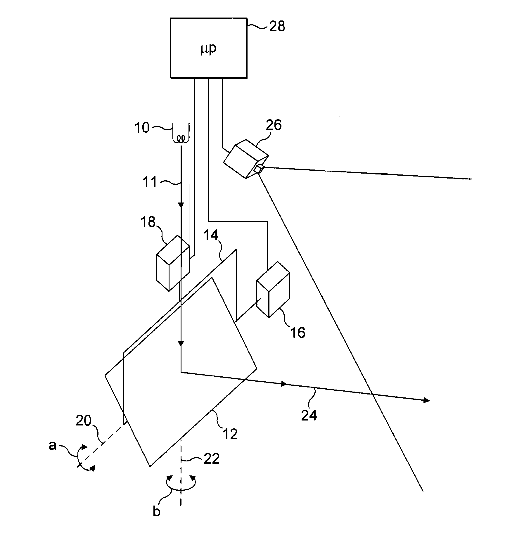
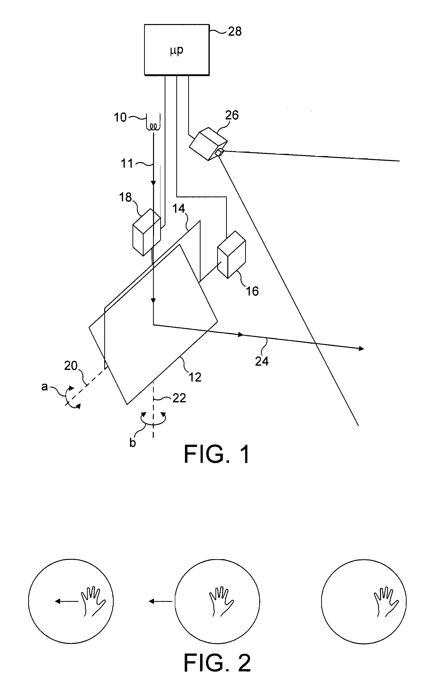
[0031]Referring to FIG. 1 of the accompanying drawing, the apparatus includes a spot lamp 10, for example a 12 volt MR16 halogen bulb with integral reflector, which produces a light beam 11. This bulb offers a very bright, feathered and focused spot having a divergence of 8 to 12° that includes a substantial component of infrared radiation. In order to dissipate heat emitted by the lamp 10, it may be mounted on a heat sink (not shown).

[0032]The beam 11 is incident on a mirror 12, which can be rotated about a horizontal axis 20 by a stepper motor 16 and about a vertical axis 22 by means of a stepper motor 18, as indicated by the double headed arrows (a) and (b). This type of mirror is well known in the field of disco lighting and we used an Acme Winner DMX scanner mirror, which is generally used for directing spotlights across a disco dance room. The stepper motors 16, 18 are controlled by a microprocessor 28 via control lines, as shown, although they may be controlled wirelessly.

[00...


PUM


Abstract

The present invention provides a lighting apparatus having a directable beam and comprising:a lamp for forming a beam of visible light;a steering mechanism, e.g. mirror for directing the beam in a desired direction;a light and movement sensor, e.g. a video camera configured to detect movement in an image formed from radiation reflected from the beam;the sensor detects movement of the whole of an object within the beam or, if only part of the object is in the beam, the whole of the part within the beam; anda processor configured to control the steering mechanism to direct the beam in accordance with movement detected in the image of the beam, e.g. movement of an object or shadow within the beam.

Description

TECHNICAL FIELD[0001]The present invention relates to a lighting apparatus in which it is possible to move a beam of light without touching the apparatus itself.BACKGROUND ART[0002]A lighting apparatus that produce a beam that can be steered in a desired direction remotely, for example using motors, is known for example in theatre lighting or in the home (see for example WO03 / 078894). However, such remote movement is mundane in nature and requires the operator to have a control unit to operate the motor to change the direction of the light beam. Also, it is hard to control the beam when the beam is directed at you or you are undertaking a task, e.g. surgery, that requires different locations to be illuminated at different times. The present invention provides a lighting apparatus and a method that allows a light beam to be directed by somebody without touching the apparatus and does not require a remote controller. Also, using the present invention, it is possible for a light beam t...

Claims


Application Information

Patent Timeline
Patent Type & Authority Applications(United States)
IPC IPC(8): F21V21/30G01J1/42G01J5/00
CPCF21V7/0008F21V17/02F21V19/02G01S17/66F21V23/0442F21V33/0052F21W2131/406F21V21/15H05B47/125Y02B20/40
Inventor WESTAWAY, ADRIAN LUCIEN REGINALD
Owner WESTAWAY ADRIAN LUCIEN REGINALD
Why Eureka
Try Eureka