Adaptive infrared retinoscopic device for detecting ocular aberrations

a technology of retinoscope and infrared light, which is applied in the field of providing medical ocular assistance and examination, can solve the problems of limited treatment options, limited clinical screening opportunities, and limited advantages of mild or early stage kc, form fruste keratoconus (ffkc),

Inactive Publication Date: 2010-08-12
AW HEALTHCARE MANAGEMENT LLC
View PDF4 Cites 91 Cited by
  • Summary
  • Abstract
  • Description
  • Claims
  • Application Information

AI Technical Summary

Benefits of technology

[0012]An embodiment of the present invention is directed toward a retinoscopic-like device for detecting high-order ocular aberrations. The device includes at least one light source that produces infrared light. An optical beam splitter is positioned such that the infrared light is directed from the light source into a patient's eye to form a point of light on the patient's retinal and reflected by the patient's retina into an image sensor such as a digital infrared camera. The image sensor detects the infrared light and produces a photorefractive image based upon the detected infrared light. The optical beam splitter is adjustable such that coaxial and eccentric photorefraction images of the patient's eye can be obtained through the adjustment. The light source may be

Problems solved by technology

Previously, treatment options were quite limited and usually relied upon the proper selection and constant fitting of rigid gas-permeable contact lens during the disease's progression.
As a result, the advantages gained by the detection of mild or early stage form of KC, Forme Fruste Keratoconus (FFKC), were limited.
However, comparatively recent developments in ophthalmic cornea treatments have altered this situation.
Even with these detection methods, short-comings exist for accurate and sensitive detection of FFKC that limit the opportunities

Method used


Image

  • Adaptive infrared retinoscopic device for detecting ocular aberrations
  • Adaptive infrared retinoscopic device for detecting ocular aberrations
  • Adaptive infrared retinoscopic device for detecting ocular aberrations

Examples


Embodiment Construction

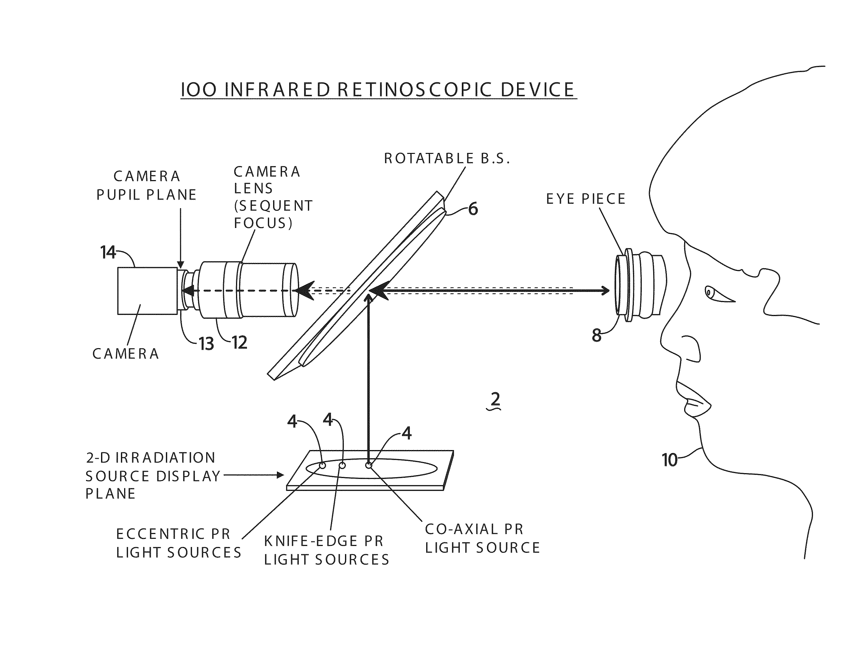
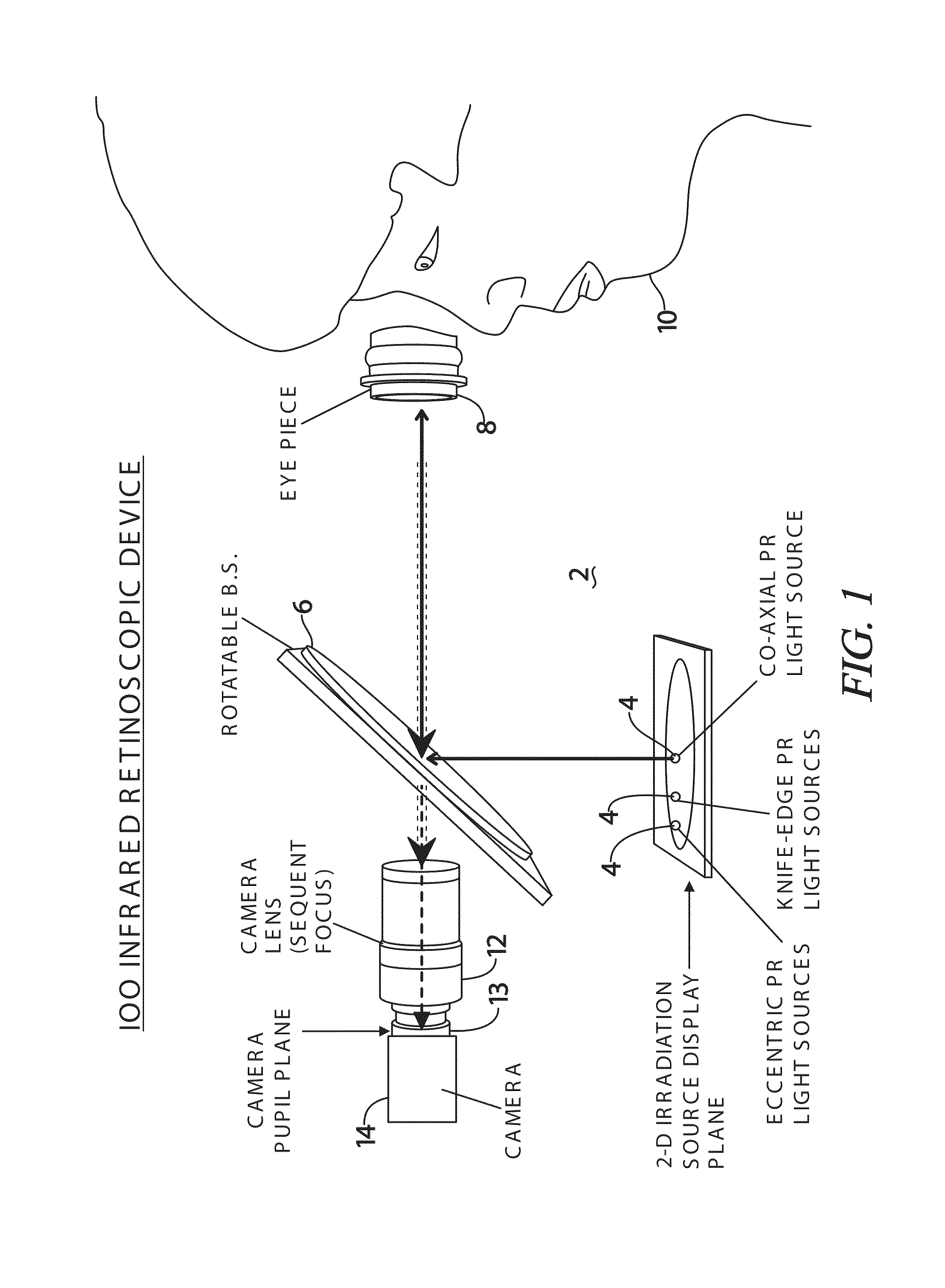
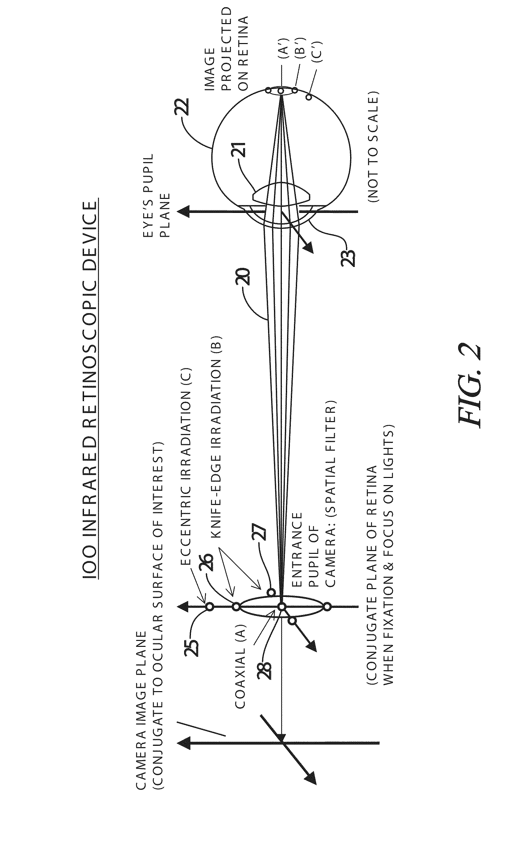
[0023]A multi-axis infrared photorefractive retinoscope constructed in accordance with an embodiment of the present invention combines simple hardware with smart software control and smart design to provide improved detection of ocular aberrations. In the present invention, photorefraction is accomplished by delivering an infrared light beam into the eye of a patient where it is bent by the ocular properties of the eye, hits the retina, and then reflects back to the camera and is detected as an image. The light is directed into the eye so that it is naturally focused to a point on the patient's retina by the eye's cornea and crystalline lens so that the photorefractive image received and produced by the camera is not an image of the surface of the retina. Rather, the photorefractive image is an image of the retinal reflex which appears on the pupil plane. This pupil image appearance depends upon the ocular properties of the eye, not the appearance of the retina itself.

[0024]An optim...


PUM


Abstract

An ocular system for detecting ocular abnormalities and conditions creates photorefractive digital images of a patient's retinal reflex. The system includes a computer control system, a two-dimensional array of infrared irradiation sources and a digital infrared image sensor. The amount of light provided by the array of irradiation sources is adjusted by the computer so that ocular signals from the image sensor are within a targeted range. Enhanced, adaptive, photorefraction is used to observe and measure the optical effects of Keratoconus. Multiple near-infrared (NIR) sources are preferably used with the photorefractive configuration to quantitatively characterize the aberrations of the eye. The infrared light is invisible to a patient and makes the procedure more comfortable than current ocular examinations.

Description

CROSS-REFERENCES TO RELATED APPLICATIONS[0001]This application is a Continuation-In-Part which claims priority from co-pending U.S. Utility patent application Ser. No. 11 / 642,226 filed Dec. 20, 2006, entitled “ADAPTIVE INFRARED RETINOSCOPIC DEVICE FOR DETECTING OCULAR ABERRATIONS”, which claims priority from co-pending U.S. Provisional Patent Application Ser. No. 60 / 751,781 filed Dec. 20, 2005, entitled “INFRARED RETINOSCOPIC DEVICE FOR DETECTING CORNEAL IRREGULARITIES AND OCULAR OPTICAL OPACITIES” which are hereby incorporated by reference.STATEMENT REGARDING FEDERALLY SPONSORED RESEARCH OR DEVELOPMENT[0002]Not ApplicableREFERENCE TO SEQUENCE LISTING OR COMPUTER PROGRAM LISTING APPENDIX[0003]Not ApplicableFIELD OF THE INVENTION[0004]The present invention is generally related to the providing of medical ocular assistance and examination. More particularly, the present invention is directed toward an ocular inspection technique and apparatus.BACKGROUND OF THE INVENTION[0005]Keratocon...

Claims


Application Information

Patent Timeline
IPC IPC(8): A61B3/103A61B3/14
CPCG06T7/0012G06T2207/10048G06T2207/20056G06T2207/30041A61B3/103A61B3/14
Inventor LEWIS, JAMES WALLER LAMBUTHWANG, MING
Owner AW HEALTHCARE MANAGEMENT LLC
Why Eureka
Try Eureka