
High strength composite materials and related processes

a composite material and high-heavy technology, applied in the field of composite materials, can solve the problems of poor dispersion of nanotubes in the matrix material, poor alignment and orientation of nanotubes in the matrix, short length of nanotubes, etc., and achieve the effect of high strength and high strength

Inactive Publication Date: 2010-08-12
CLEVELAND STATE UNIVERSITY
View PDF8 Cites 66 Cited by
  • Summary
  • Abstract
  • Description
  • Claims
  • Application Information

AI Technical Summary

Benefits of technology

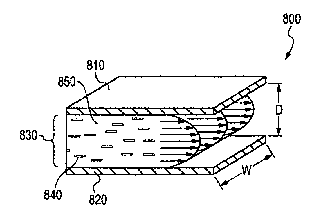
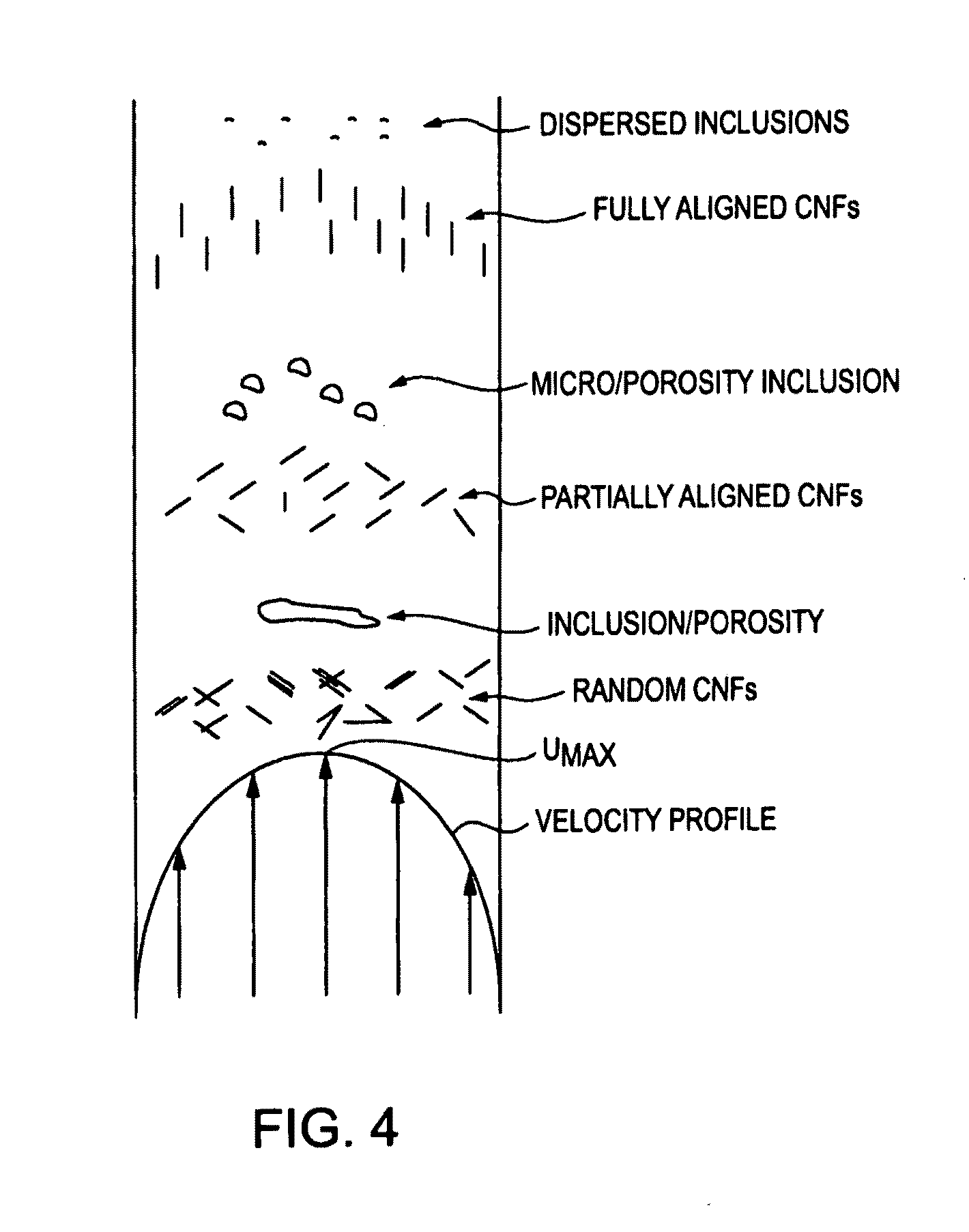
[0011]In a first aspect, the present invention provides a process for producing a high strength composite material comprising an effective amount of at least one type of nanostructure having an aspect ratio greater than 1.0, and a matrix material. The process comprises providing a matrix material. The process also comprises heating the matrix material such that the matrix material is flowable. The process further comprises providing at least one type of nanostructure having an aspect ratio greater than 1.0. The process also comprises combining an effective amount of the at least one type of nanostructure with the matrix material. The process further comprises flowing in a laminar fashion, the combined amount of nanostructures with the matrix material, to thereby cause at least a majority of the nanostructures to adopt a parallel orientation in the matrix material. The process also comprises solidifying the composite material while the nanostructures are in the parallel orientation in the matrix material to thereby produce the high strength composite material.

Problems solved by technology

Unfortunately, composite materials and specifically, methods utilizing nanotubes or other nanostructures to improve the properties of materials by forming nano-composite matrices, particularly those based upon glass, ceramic, or metal; have met various challenges and shortcomings.
These shortcomings include poor dispersion of the nanotubes in the matrix material, primarily due to Van der Waals' forces; poor alignment and orientation of the nanotubes in the matrix; short lengths of the nanotubes relative to defect sizes in the composite matrices; and difficulties associated with handling randomly oriented nanotubes in an industrial scale process.
Therefore, it is believed that this strategy would be costly to implement on a large scale industrial level.
In addition, this strategy is likely limited to metal matrix materials and could not be used for glass or ceramic matrix materials.
Furthermore, due to the methods adopted by Cha et al., this work does not address problems of poor dispersion of nanotubes in the matrix material, poor alignment and orientation of the nanotubes in the matrix, short lengths of the nanotubes relative to defect sizes in the composite material, and difficulties associated with handling the nanotubes in a large scale process.
Although providing a high strength yarn product, this technology would again, be difficult to implement at an industrial level, costly to undertake, and essentially be limited to forming yarns or collections of single material fibers.
Furthermore, this technology does not relate to composite materials using glass, ceramic, or metal matrices.
Nor does this work provide a practical strategy for handling the exceedingly small nanotubes.
Greywall did not address difficulties associated with dispersing the carbon particles in the medium since Greywall relies upon a drawing operation to align and assemble the particles before removing the medium.
Although satisfactory in certain regards, the use of a drawing operation to align particles is not always possible with all materials or in all applications.
In addition, Greywall's work is silent with regard to reducing defects in the final material.
However, such methods have only produced marginal improvements and in some cases, have only resulted in a weaker matrix by introducing additional inclusions and porosity into the resulting material.
In summary, currently known methods of incorporating randomly oriented nanotubes and / or lower performance and much lower cost nanofibers in composite materials, result in isotropic matrices with only moderate improvements in the properties and performance of the resulting materials.
The resulting materials fail to exhibit the projected quantum improvements based on the superior directional properties of the nanotubes and the nanofibers.

Method used


Image

  • High strength composite materials and related processes
  • High strength composite materials and related processes
  • High strength composite materials and related processes

Examples


Embodiment Construction

[0036]The present invention and preferred embodiments relate to incorporating or imbedding, dispersing and orienting nanostructures such as nanofibers and / or nanotubes (NF / NT) in glass, fused silica(s), and metal matrices and other materials to produce exceptionally strong nano-composite glass fibers, metal wires, sheets, plates, and structures with highly enhanced physical, thermal and electrical properties. In certain embodiments of the invention, the nanofibers and / or nanotubes are highly aligned or otherwise uniformly oriented in the material matrix.

[0037]The present invention provides in a broad aspect, a unique and ready strategy to disperse, disentangle or separate if necessary, and / or selectively align a collection of nanostructures in a matrix material. The strategy transforms the combined matrix material and nanomaterials into a flowable state, and then induces the combination to then flow. Flow can occur within nearly any type of channel, duct, or enclosure. It is contemp...


PUM

PropertyMeasurementUnit
Temperatureaaaaaaaaaa

Abstract

Composite materials exhibiting very high strength properties and other characteristics are disclosed. The materials comprise one or more nanomaterials dispersed within one or more matrix materials. The nanomaterials can be in a variety of forms, such as for example, carbon nanotubes and / or nanofibers. The matrix material can be glass, fused silicas, or metal. Also disclosed are various processes and operations to readily disperse and uniformly align the nanotubes and / or nanofibers in the flowing matrix material, during production of the composite materials.

Description

CROSS-REFERENCES TO RELATED APPLICATION[0001]The present application claims priority upon U.S. provisional application Ser. No. 60 / 812,389 filed Jun. 9, 2006, which is also hereby incorporated by reference.BACKGROUND[0002]The present invention relates to composite materials using nanomaterials or nanostructures that exhibit high strength properties and other beneficial characteristics. The invention also relates to various processes for producing such composite materials. The invention finds particular application in conjunction with composite materials utilizing certain nanostructures such as nanotubes and nanofibers, and will be described with particular reference thereto. However, it is to be appreciated that the present invention is also amenable to other like applications. For example, the invention also relates to composite materials and processes that employ other nanostructures besides, or in addition to, nanotubes and nanofibers.[0003]The discovery of nanomaterials and part...

Claims


Application Information

Patent Timeline
IPC IPC(8): B32B15/14B32B17/12D02G3/00C03C14/00C03B37/012
CPCC03C4/12C03C13/00Y10T428/12542C03C2213/04Y10T428/2927C03C14/002Y10T428/249924Y10T428/249927Y10T428/249929
Inventor NAYFEH, TAYSIR H.
Owner CLEVELAND STATE UNIVERSITY
Learn More