
Methods and devices for occlusion of an atrial appendage

a technology of atrial appendage and occlusion, which is applied in the field of methods and devices for occlusion or ligation of atrial appendages, can solve the problems of affecting the patient's health, affecting the patient's daily life, and causing bleeding and lifestyle compromises,

Inactive Publication Date: 2010-08-12
STEWART MARK T +13
View PDF6 Cites 55 Cited by
  • Summary
  • Abstract
  • Description
  • Claims
  • Application Information

AI Technical Summary

Benefits of technology

[0010]Other embodiments of the invention provide a clip occluder that can be positioned around the left atrial appendage. The clip occluder can include a clip hinge coupled to an upper clip jaw and a lower clip jaw. The clip occluder can include a clip lock. A clip applicator can position the clip occluder with respect to the left atrial appendage. The clip applicator can include a clip actuator coupled to the clip occluder by an actuator suture. The actuator suture can control a distance between the upper clip jaw and the lower clip jaw. The clip applicator can be removably coupled to the clip occluder with a retention suture.

Problems solved by technology

Embolic stroke is also a major cause of disability.
Although somewhat effective, there are numerous side effects, including bleeding and lifestyle compromises.
Pharmacological therapies (such as Warfarin®) are not well tolerated by patients.
The introduction of biomaterials into the left atrial appendage has resulted in the biomaterials eventually breaking down by resulting in clot formation.
However, any foreign device left in the chamber of the heart is a potential thrombosis-generating site.
In addition, biomaterials are known to eventually break down and result in clotting.
This is done under general anesthesia and may result in additional trauma to the patient.
While endoscopic or percutaneous approaches reduce the invasiveness of the surgical procedure, the above-described approaches have inherent limitations.
Surgical removal of the left atrial appendage is very invasive and often results in loss of atrial hormones, such as atrial natriuretic peptide (ANP), and significant bleeding.

Method used


Image

  • Methods and devices for occlusion of an atrial appendage
  • Methods and devices for occlusion of an atrial appendage
  • Methods and devices for occlusion of an atrial appendage

Examples


Embodiment Construction

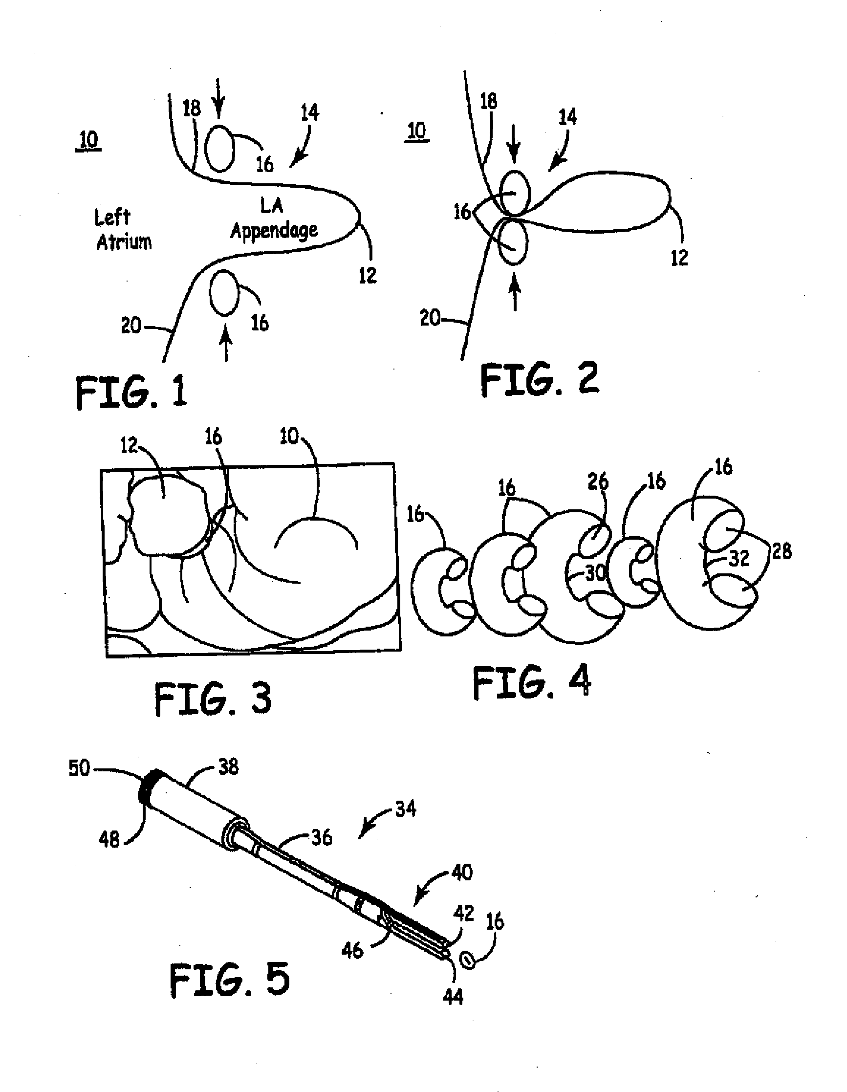
[0117]FIG. 1 illustrates an outline of the atrium 10 of the heart with the left atrial appendage 12 protruding therefrom. FIG. 1 also illustrates one embodiment of an occluder 14 forming a ring 16 that is placed in a position to surround the left atrial appendage 12 adjacent to a left atrial appendage base 18, where the left atrial appendage 12 is attached to the heart 20. In some embodiments, the ring 16 can be constructed of an elastic material to allow it to be stretched into an open position, as shown in FIG. 1. The ring 16 can be allowed to return to a closed position, as shown in FIG. 2, to bear against the tissue of the left atrial appendage 12 in order to close off any interior connection between the atrium 10 and the left atrial appendage 12.

[0118]FIG. 3 illustrates the ring 16 attached to a patient's heart 20 to isolate the left atrial appendage 12 from the atrium 10. In some embodiments, the material of the ring 16 can be biocompatible to allow the ring 16 to be left on t...


PUM


Abstract

Some embodiments of the invention provide a system for occluding a left atrial appendage of a patient. Some embodiments of the system can include a ring occluder that can be positioned around the left atrial appendage and a ring applicator to position the ring occluder with respect to the left atrial appendage. One embodiment discloses a method of accessing endocardial surfaces of the heart through the atrial appendage. Additional embodiments of the invention provide a clip occluder that can be positioned around the left atrial appendage. A clip applicator can position the clip occluder with respect to the left atrial appendage.

Description

CROSS-REFERENCE TO RELATED APPLICATIONS[0001]This application is a continuation of U.S. application Ser. No. 11 / 788,261, filed Apr. 19, 2007, which is a continuation-in-part of U.S. application Ser. No. 11 / 155,699, filed Jun. 17, 2005, which claims the benefit of U.S. Application Ser. Nos. 60 / 581,223, filed on Jun. 18, 2004, and 60 / 685,681, filed on May 27, 2005, all of which are incorporated herein by reference in their entirety. This application also claims the benefit of U.S. Application Ser. No. 60 / 795,752 filed Apr. 28, 2006, the disclosure of which is also incorporated herein by reference in its entirety.FIELD OF THE INVENTION[0002]The invention relates to methods and devices for occlusion or ligation of an atrial appendage.BACKGROUND OF THE INVENTION[0003]Embolic stroke is the nation's third leading killer for adults. Embolic stroke is also a major cause of disability. The most common cause of embolic stroke is thrombus formation in the left appendage on the atrium. In almost...

Claims


Application Information

Patent Timeline
Patent Type & Authority Applications(United States)
IPC IPC(8): A61B17/128A61B17/122
CPCA61B17/0057A61B17/12A61B17/12009A61B17/12013A61B17/122A61B2017/306A61B17/1285A61B19/54A61B2017/00243A61B2017/00575A61B2017/12018A61B17/128A61B90/39
Inventor STEWART, MARK T.LUTTERMAN, ALISONFRANCISCHELLI, DAVID E.LEUER, LEONARD H.HAEG, DANEIL C.STEINBRINK, MARIE T.BRISCOE, RODERICK E.DAIGEL, TOM P.WARMAN, EDUARDO N.ROTHSTEIN, PAUL T.FALKNER, PHILLIP C.HETTRICK, DOUGLAS A.KIM, DAVID J.S.CHRISTIAN, STEVEN C.
Owner STEWART MARK T
Learn More