Apparatus and methods for treating congestive heart disease

a congestive heart disease and appendix technology, applied in the field of appendix and methods for treating congestive heart disease, can solve the problems of reducing cardiac output, causing patients to go into arf, and causing excess fluid in the body, so as to improve renal function and improve blood flow to the kidneys

Inactive Publication Date: 2008-02-26
ANGIODYNAMICS INC
View PDF151 Cites 294 Cited by
  • Summary
  • Abstract
  • Description
  • Claims
  • Application Information

AI Technical Summary

Benefits of technology

[0015]The present invention provides methods and apparatus for treating and managing ARF without administering high doses of drugs or dehydrating the patient by improving blood flow to the kidneys, thereby enhancing renal function.
[0019]To facilitate the advancement of the catheter into the patient's coronary artery, a guiding catheter having a distal tip may be first percutaneously introduced into the abdominal aorta of a patient by the Seldinger technique through the brachial or femoral arteries. The catheter is advanced until the preshaped distal tip of the guiding catheter is disposed within the aorta adjacent the ostium of the renal arteries. A balloon catheter embodying features of the invention may then be advanced through the guiding catheter into the patient's abdominal aorta over a guidewire until the balloon on the catheter is disposed at the desired region of the patient's artery. In specific embodiments, the use of a guiding catheter is unnecessary. The advancement of the catheter over a guidewire is sufficient to achieve adequate placement.
[0021]The balloon may be formed using either compliant or non-compliant materials, preferably compliant. Most optimally, the balloon material is chosen so that inflation of the balloon to a volume sufficient to occlude the aorta, i.e., to a diameter of between 15 and 35 mm, will create a sufficient pressure within the balloon so as to provide the balloon with some degree of mechanical rigidity and to likewise apply a small amount of outward radial force to the aortic wall so as to provide positional and orientational stability to the balloon. Such a pressure is typically between about 4 and about 20 psi. Materials that can achieve such behavior include synthetic polyisoprene and thermoplastic urethane. Material durometer and tensile modulus must be selected appropriately so as to allow for the above properties to be exhibited with a practical balloon-wall thickness. Material with a shore hardness of about 70 A to about 100 A, preferably about 80 A to about 90 A are appropriate. For example, thermoplastic urethane such as Dow Pellethane 2363-80A, which has a Shore hardness of 80 A, a tensile modulus of 1750 psi at 300% elongation and an ultimate elongation of 550%, can be used for forming the balloon. Balloons may be formed by dipping a shaped mandrel into a mixture of urethane dissolved in a solvent, such as tetrahydrofuran. The mandrel should be shaped so as to produce an uninflated balloon with a diameter of between 3 and 8 mm. The dipping process should be repeated so as to produce a balloon with an uninflated wall thickness of between 0.002 in. and 0.010 in. Alternatively, the balloon can be formed by first melt-extruding a length of tubing and then blow-molding the tube into a balloon form. Dimensions of the tubing and mold would be chosen to achieve the same diameter and thickness described above.
[0025]The balloon of the catheter is inflated to retain the outlet end of the catheter in position in a renal artery and to prevent backflow of blood into the abdominal aorta. Alternatively, a pair of balloons may be selectively inflated to isolate the region of the abdominal aorta adjacent to the renal arteries. In yet another embodiment, a center balloon is disposed within an isolated region of the abdominal aorta defined by the distal and proximal balloons, and the extracorporeal pump is employed to inflate the third balloon to increase flow to the renal arteries.
[0026]In any of the foregoing cases it is expected that blood passing through the catheter, or trapped within the isolated region of the abdominal aorta, will have a higher pressure and flow rate than blood reaching the renal arteries via the abdominal aorta. This, in turn, is expected to improve renal blood flow without the administration of systemic drug doses. The enhanced renal blood flow is expected to provide a proportional increase in renal function, thereby reducing fluid retention.
[0030]For passive perfusion, apparatus is provided that constricts the abdominal aorta proximal to the renal arteries. In this case, a stent or other device is disposed within the aorta to cause a narrowing of the aorta proximal to the renal arteries, thereby creating a pressure differential across the apparatus that is expected to improve blood flow rate to the renal arteries.

Problems solved by technology

A traumatic event, such as hemorrhage, gastrointestinal fluid loss, or renal fluid loss without proper fluid replacement may cause the patient to go into ARF.
Additionally, reduced cardiac output caused by cardiac shock, congestive heart failure, pericardial tamponade or massive pulmonary embolism creates an excess of fluid in the body.
This reduced flow can in turn result in the retention of excess fluid in the patient's body, leading for example, to pulmonary and cardiac edema.
The appearance of ARF significantly increases mortality.
Many of these drugs, when administered in systemic doses, have undesirable side-effects.
Additionally, many of these drugs would not be helpful in treating other causes of ARF.
Mechanical treatments, such as hemodialysis, however, generally have not been used for long-term management of CHF.
Such mechanical treatments would also not be help for patients with strong hearts suffering from ARF.
Poor patient compliance is a major cause of refractoriness to treatment.

Method used


Image

  • Apparatus and methods for treating congestive heart disease
  • Apparatus and methods for treating congestive heart disease
  • Apparatus and methods for treating congestive heart disease

Examples


Embodiment Construction

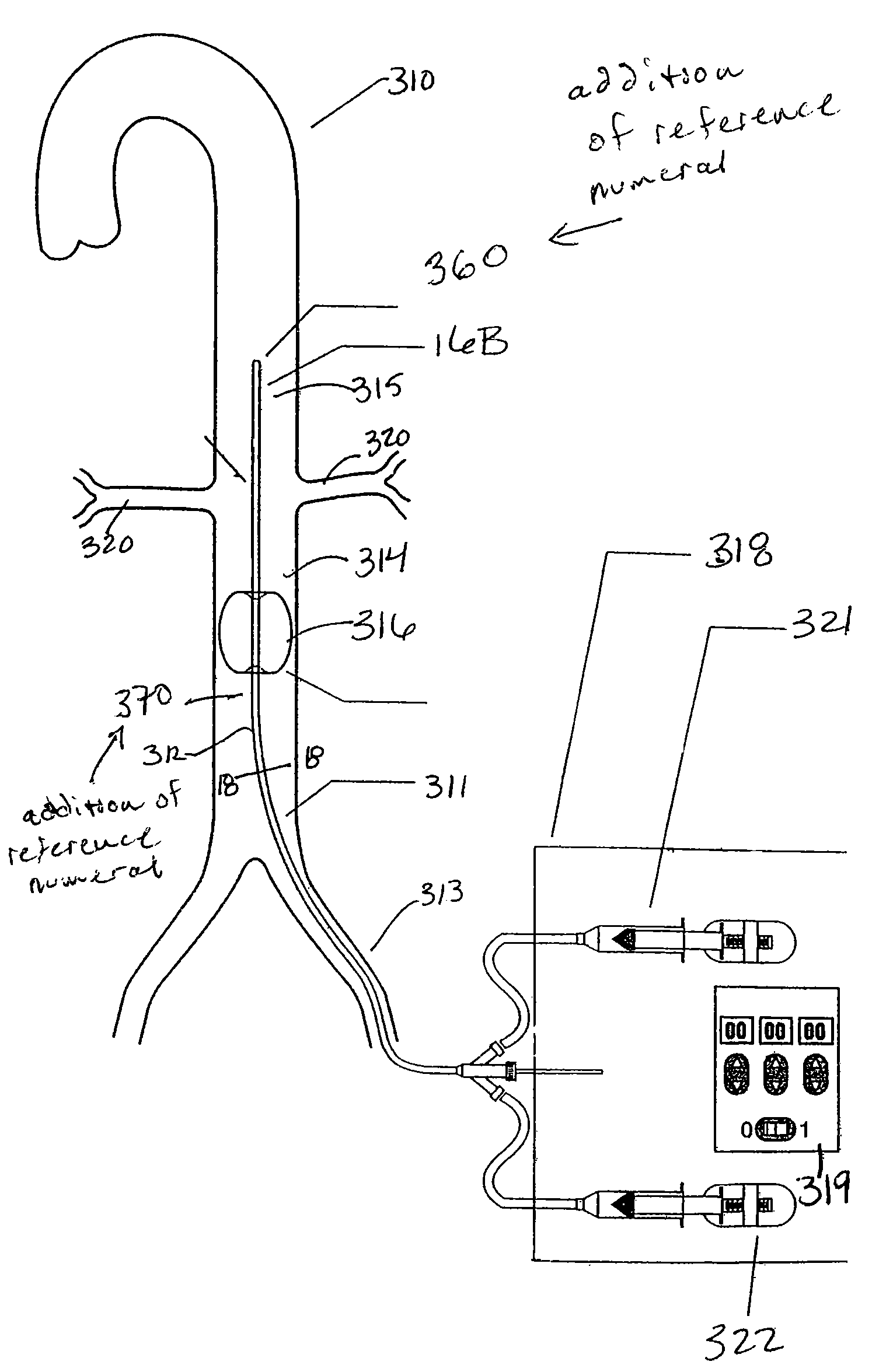
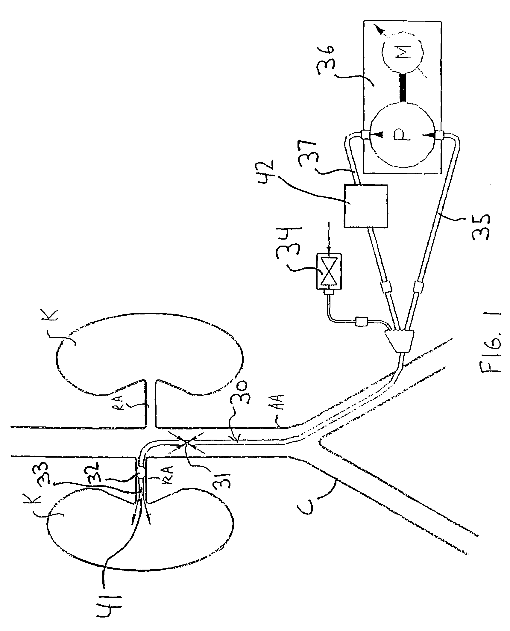
[0053]The present invention provides several apparatus for treating patients suffering from congestive heart failure (“CHF”) by improving renal blood flow and renal function. Some preferred embodiments of the present invention provide active perfusion of the renal arteries, and comprise a catheter and an extracorporeal pump. The catheter and pump may be used either to withdraw autologous blood from the patient's body and reperfuse that blood into the patient's renal arteries, or to isolate a region of the abdominal aorta and cause a pressure differential within-the isolated region that causes perfusion of the renal arteries.

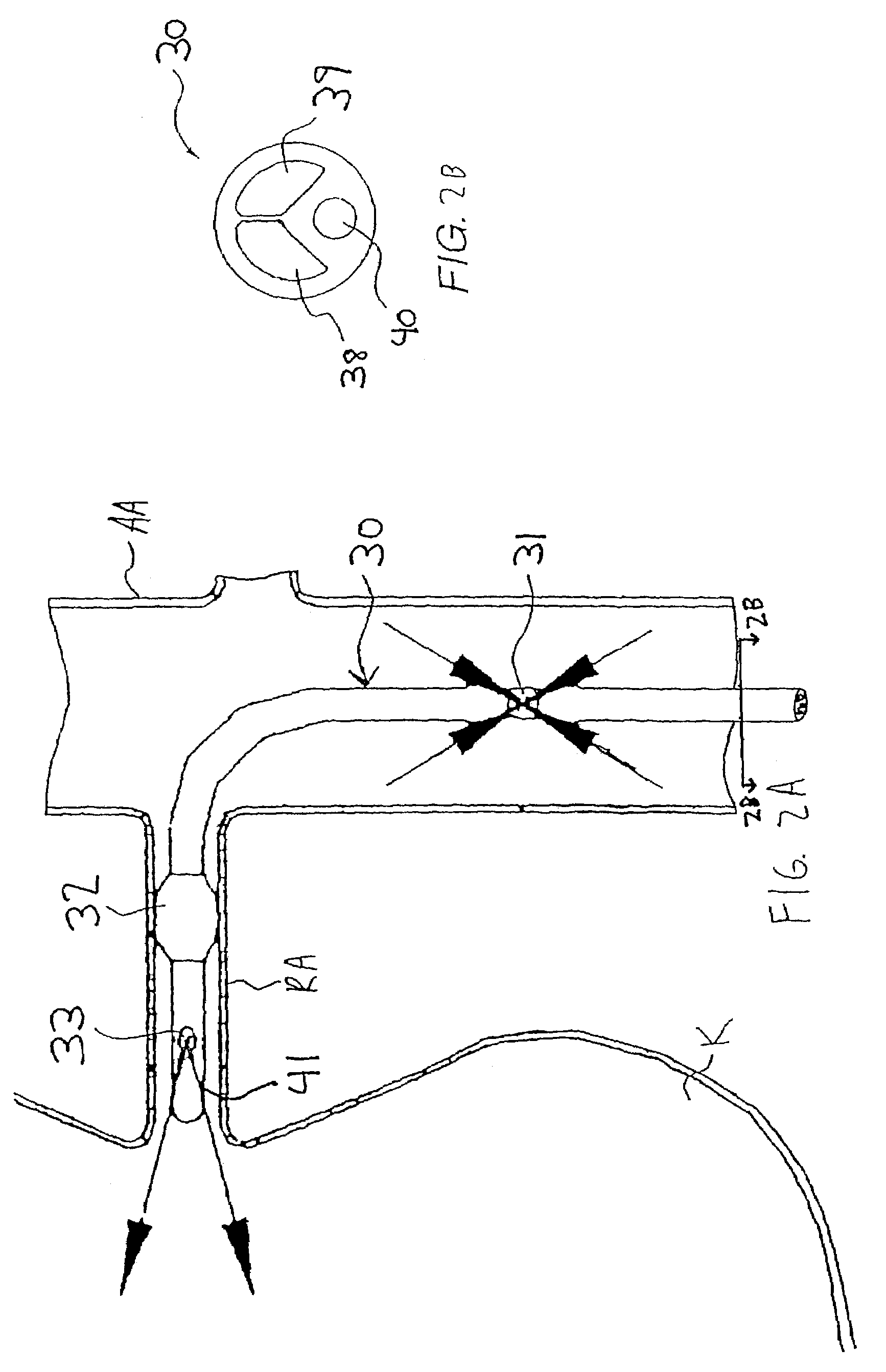
[0054]Other preferred embodiments of the present invention cause a constriction in the abdominal aorta downstream (proximal) of the renal arteries, so that the pressure differential resulting from the constriction preferentially perfuses the renal arteries.

[0055]Referring to FIGS. 1 and 2A-2B, a first illustrative embodiment of an active perfusion apparatus of th...


PUM


Abstract

Methods and apparatus are provided for treating congestive heart by actively or passively enhancing perfusion to the renal arteries. A first embodiment comprises a specially configured balloon catheter and extracorporeal pump, wherein the pump operates in a “once-through” fashion or alternating volume displacement mode. In another embodiment the catheter includes a pair of balloons to isolate a region of the aorta, and a third balloon that directs flow into the renal arteries. In still further embodiments, a stent or cuff having a constricted region is deployed in or around the aorta, respectively, to create a backpressure upstream of the stent or cuff. Methods of enhancing renal perfusion also are provided.

Description

CROSS-REFERENCE TO RELATED APPLICATIONS[0001]This application is a continuation of copending U.S. patent application Ser. No. 09 / 562,493 filed on May 1, 2000, incorporated by reference herein, which is a continuation in part of U.S. patent application Ser. No. 09 / 229,390 filed on Jan. 11, 1999 now U.S. Pat. No. 6,749,598, incorporated by reference herein.STATEMENT REGARDING FEDERALLY SPONSORED RESEARCH OR DEVELOPMENT[0002]Not ApplicableINCORPORATION-BY-REFERENCE OF MATERIAL SUBMITTED ON A COMPACT DISC[0003]Not ApplicableBACKGROUND OF THE INVENTION[0004]Acute renal failure (“ARF”) is an abrupt decrease in the kidney's ability to excrete waste from a patient's blood. This change in kidney function may be attributable to many causes. A traumatic event, such as hemorrhage, gastrointestinal fluid loss, or renal fluid loss without proper fluid replacement may cause the patient to go into ARF. Patient's may also become vulnerable to ARF after receiving anesthesia, surgery, α-adrenergic arg...

Claims


Application Information

Patent Timeline
Patent Type & Authority Patents(United States)
IPC IPC(8): A61M31/00A61M29/00A61B17/00A61B17/06A61B17/12A61B17/22A61F2/06A61M1/10A61M1/12A61M1/36A61M25/00
CPCA61M1/101A61M1/1072A61M1/3653A61M25/00A61M25/10A61M27/002A61B17/1219A61B17/12036A61B17/12045A61B17/12109A61B17/12136A61M1/125A61M1/3659A61B17/12013A61B2017/00243A61B2017/061A61B2017/22054A61F2002/068A61M25/0075A61M25/1011A61M2025/1052A61M2210/1082A61M2210/125A61B2017/00898A61M1/3613A61M60/113A61M60/833A61M60/414A61M60/38A61M60/232A61M60/279A61M60/13A61M60/258A61M60/867A61M1/3623A61M60/33A61M60/148
Inventor KEREN, GADSHMULEWITZ, ASCHERSPENSER, BENJAMINARAD, MICHAELKESTEN, RANDY JPESOTCHINSKY, SOPHIAROSENTHAL, MICHAEL H.KRAMER, ANDREW W.PAYNE, SAM G.
Owner ANGIODYNAMICS INC
Why Eureka
Try Eureka