
Percutaneous valve prosthesis and system and method for implanting same

a technology of heart valve and prosthesis, which is applied in the field of heart valve prosthesis, can solve the problems of thromboembolic complications, catastrophic valve failure, and high risk of valve replacement surgery, and achieve the effect of minimizing the gradient across the valv

Inactive Publication Date: 2009-12-10
EDWARDS LIFESCI CARDIAQ
View PDF101 Cites 295 Cited by
  • Summary
  • Abstract
  • Description
  • Claims
  • Application Information

AI Technical Summary

Benefits of technology

[0026]It is another object of this invention to provide maximal valve area to the out flow tract of the left ventricle, thus minimizing the gradient across the valve, by using a supra annular implant of the valve piece to the valve cage stent.

Problems solved by technology

Mechanical valves require lifelong anticoagulant medication to prevent clot formation around the valve, which can lead to thromboembolic complications and catastrophic valve failure.
Valve replacement surgery is a highly invasive operation with significant concomitant risk.
Risks include bleeding, infection, stroke, heart attack, arrhythmia, renal failure, and adverse reactions to the anesthesia medications, as well as sudden death.
PVT's device suffers from several drawbacks.
Deployment of PVT's stent has several drawbacks, including that there is very little control over its deployment.
This lack of control can endanger the coronary ostea above the aortic valve and the anterior leaflet of the mitral valve below the aortic valve.
Another drawback of the PVT device is its relatively large cross-sectional delivery profile.
Considering they have to be durable, the materials for the valve and the stent are very bulky, thus increasing the profile of the device.
The PVT system's stent / valve combination is mounted onto a delivery balloon, making retrograde delivery through the aorta challenging.
An antegrade transseptal approach may therefore be needed, requiring puncture of the septum and routing through the mitral valve, which significantly increases complexity and risk of the procedure.
Very few cardiologists are currently trained in performing a transseptal puncture, which is a challenging procedure by itself.
Another drawback of the PVT device is its lack of fixation provision.
For this to work, sufficient dilatation of the valve area has to be achieved; but this amount of dilation can cause damage to the annulus.
Also, due to its inability to have an active fixation mechanism, the PVT device cannot be used to treat aortic regurgitation.
Another drawback to this system is that it does not address the leakage of blood around the implant, after its implantation.
Standard self-expanding systems have very poor accuracy in deployment, however.
It is therefore often impossible to know where the ends of the stent will be with respect to the native valve, the coronary ostia, and the mitral valve.
Another drawback of prior art self-expanding replacement heart valve systems is their lack of radial strength.
However, when the stent has a valve fastened inside it, as is the case in aortic valve replacement, the anchoring of the stent to vessel walls is significantly challenged during diastole.
Moreover, a self-expanding stent without sufficient radial force will end up dilating and contracting with each heartbeat, thereby distorting the valve, affecting its function and resulting in dynamic repositioning of the stent during delivery.
Stent foreshortening or migration during expansion may lead to improper alignment.
Additionally, the stent disclosed in U.S. Pat. No. 6,425,916 to Garrison simply crushes the native valve leaflets against the heart wall and does not engage the leaflets in a manner that would provide positive registration of the device relative to the native position of the valve.
This increases an immediate risk of blocking the coronary ostia, as well as a longer-term risk of migration of the device post-implantation.
Tissue may protrude through these gaps, thereby increasing a risk of improper seating of the valve within the stent.
This mechanism addresses the fixation issue; however, considering the irregular shape of the aortic annulus there is a real potential for deforming the prosthetic valve annulus; this may require additional balloon angioplasty to give it its final shape, and also make the new valve more prone to fatigue and fracture.
Moreover if full expansion of the stent is prone to deformation, the leaflet coaptation of the valve will be jeopardized.
The valve piece connects to the anchor piece in such a fashion that it will reduce the effective valve area considerably.
Garrison's valve is also implanted in the inner portion of the stent, compromising the effective valve outflow area.
The duration of function and physical deterioration of these new valves have not been addressed.

Method used


Image

  • Percutaneous valve prosthesis and system and method for implanting same
  • Percutaneous valve prosthesis and system and method for implanting same
  • Percutaneous valve prosthesis and system and method for implanting same

Examples


Embodiment Construction

[0058]In describing preferred embodiments of the present invention illustrated in the drawings, specific terminology is employed for the sake of clarity. However, the invention is not intended to be limited to the specific terminology so selected, and it is to be understood that each specific element includes all technical equivalents that operate in a similar manner to accomplish a similar purpose.

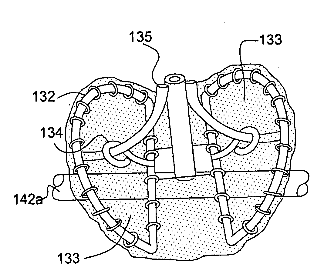
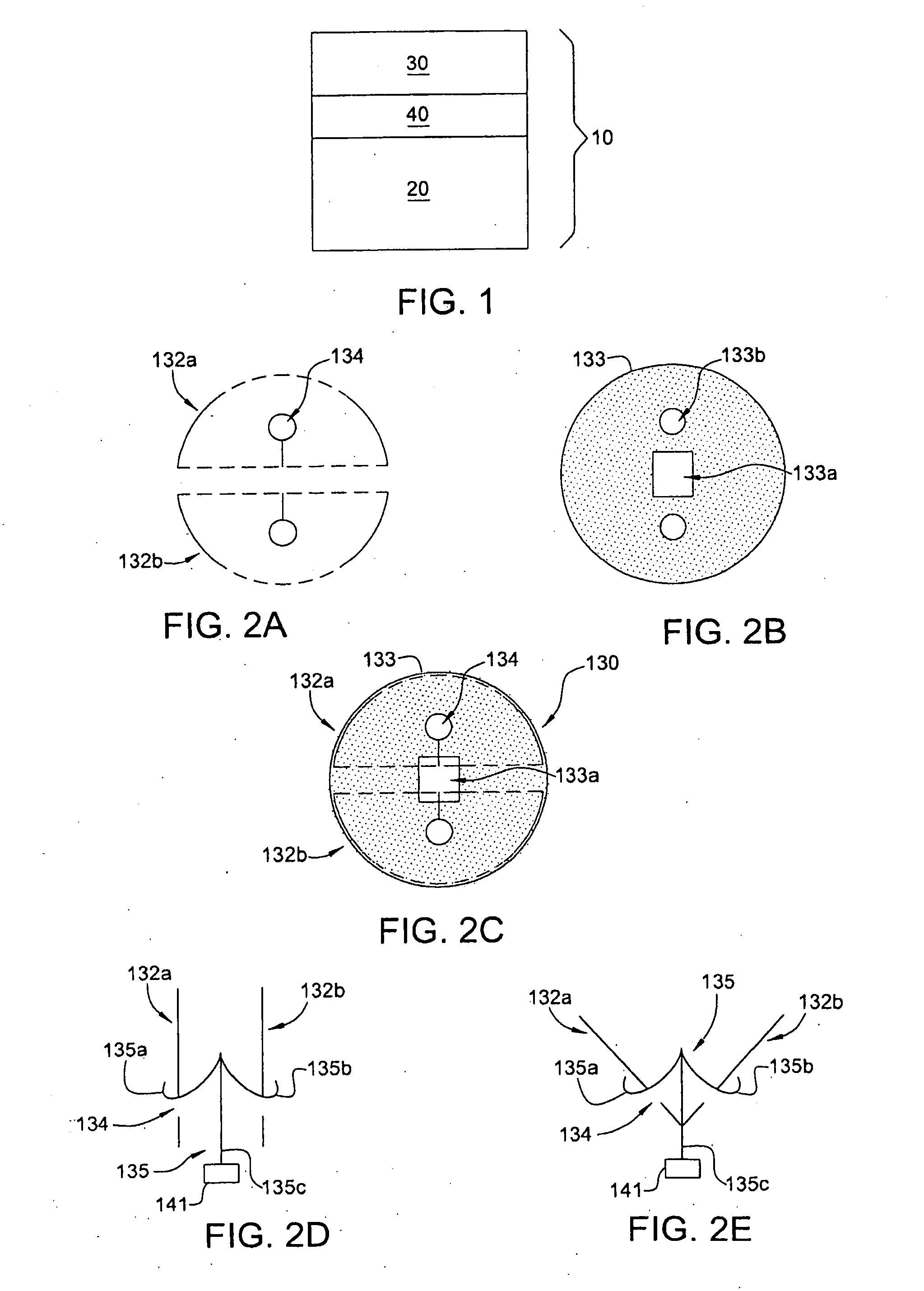
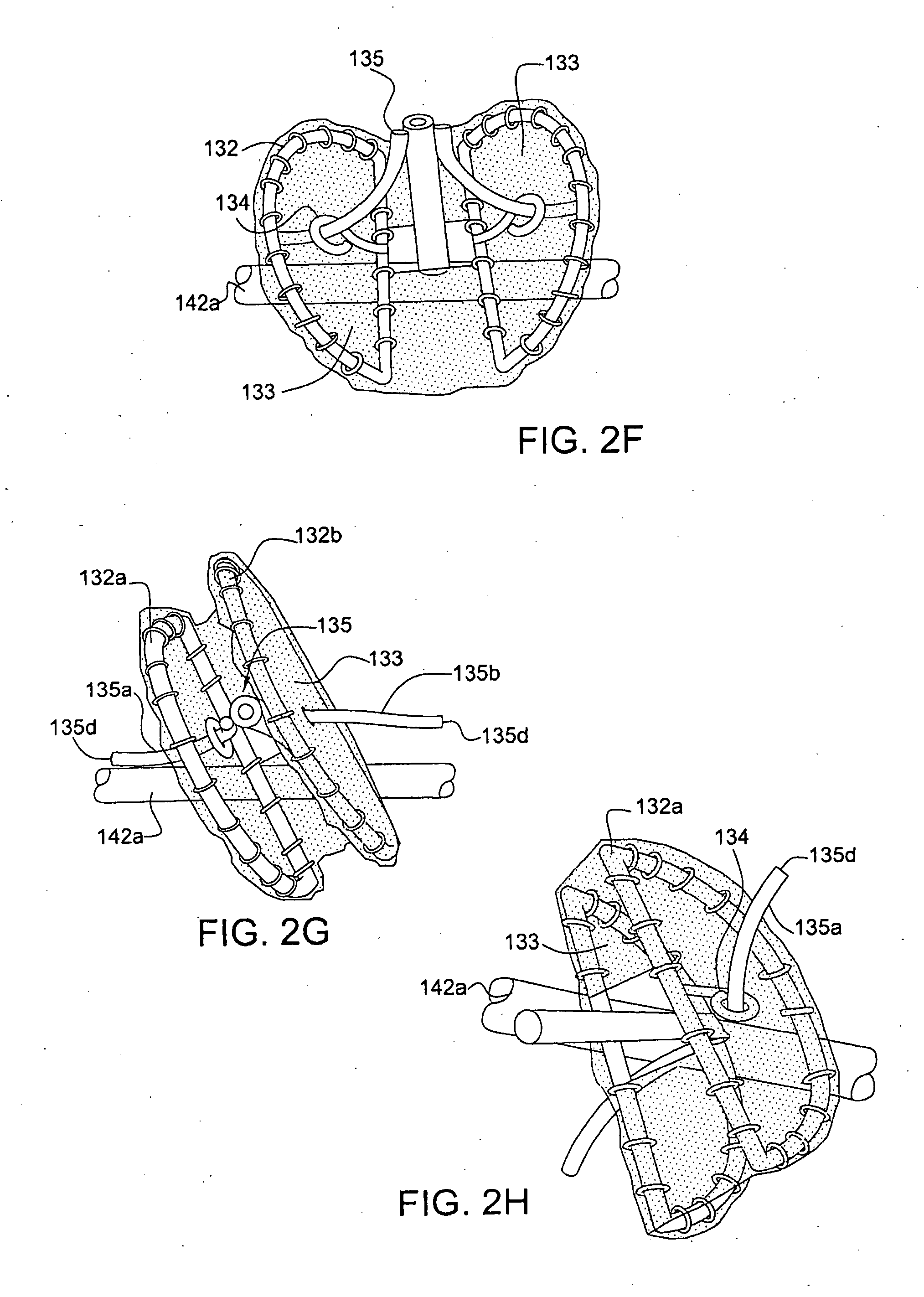
[0059]The present invention relates to heart valve prostheses that can be implanted percutaneously by means of a catheter from a remote location without opening the chest cavity. As shown in FIG. 1, the valve prosthesis 10 comprises two parts, (1) a valve cage stent 20 constructed to be implanted in the planar axis of the native valve annulus, (2) an elastic and compressible valve 30, and (3) an attachment mechanism for attaching the valve 30 to the superior rim of the above mentioned valve cage stent 20. In accordance with the present invention, two types 110 and 210 of heart valve prost...


PUM


Abstract

A heart valve prosthesis includes a cylindrical valve cage stent constructed to be implanted percutaneously in the planar axis of a native valve annulus, an elastic and compressible, multi-leaflet valve insertable percutaneously into the body, and an attachment mechanism for attaching the valve to the superior rim of the valve cage stent. The valve can be of a bi-leaflet or a tri-leaflet type and includes a valve frame made from a memory metal and a tissue cover attached to the valve frame. The valve cage stent is self-expanding or balloon expandable, made respectively from memory metal or stainless steel but otherwise structurally the same.

Description

CROSS-REFERENCE TO RELATED APPLICATIONS[0001]The present patent application is based on, and claims priority from, U.S. provisional Application No. 60 / 833,791, filed Jul. 28, 2006, which is incorporated herein by reference in its entirety.BACKGROUND OF THE INVENTION[0002]1. Field of the Invention[0003]The present invention relates to heart valve prostheses, preferably to aortic valve prostheses. More specifically, the invention relates to heart valve prostheses that can be implanted percutaneously by means of a catheter from a remote Location without opening the chest cavity.[0004]2. Related Art[0005]Heart valve surgery is used to repair or replace diseased heart valves. Valve surgery is an open-heart procedure conducted under general anesthesia. An incision is made through the patient's sternum (sternotomy), and the patient's heart is stopped while blood flow is rerouted through a heart-lung bypass machine.[0006]Valve replacement may be indicated when there is a narrowing of the na...

Claims


Application Information

Patent Timeline
IPC IPC(8): A61F2/06
CPCA61F2/2418A61F2/2436A61F2230/0054A61F2250/006A61F2/2439A61F2220/0016
Inventor QUADRI, ARSHAD
Owner EDWARDS LIFESCI CARDIAQ
Learn More