Process for solid oxide fuel cell manufacture

a solid oxide fuel cell and manufacturing technology, applied in the field of solid oxide fuel cell manufacturing, can solve the problems of requiring several hours to sinter the electrolyte and electrode structure, affecting the commercialization of sofc devices, and affecting the quality of sofc devices, etc., to achieve the effect of convenient manufacturing of solid oxide fuel cells

Inactive Publication Date: 2009-02-03
TRUSTEES OF BOSTON UNIV +1
View PDF47 Cites 21 Cited by
  • Summary
  • Abstract
  • Description
  • Claims
  • Application Information

AI Technical Summary

Benefits of technology

[0007]Additionally, the method of the invention harmonizes and minimizes the deviation among the thermophysical properties of the electrolyte and electrode structures. This harmonization reduces and minimizes the temperature gradient within the cell such that the structure can be uniformly heated and fired during the thermal cycle. The multilayer structure is also unlikely to distort and fracture by minimizing the temperature gradient in the cell. A multilayer fuel cell can also be manufactured by the present method in an order of magnitude less time than standard processes.

Problems solved by technology

An obstacle to commercializing SOFC devices is the substantial cost associated with their manufacture.
This cost is an order of magnitude higher than fabricating a comparable gas turbine.
This rate can require several hours to sinter the electrolyte and electrode structures.
Thus, manufacturing a fuel cell by such processes is entirely inefficient and expensive.

Method used


Image

  • Process for solid oxide fuel cell manufacture
  • Process for solid oxide fuel cell manufacture
  • Process for solid oxide fuel cell manufacture

Examples


Embodiment Construction

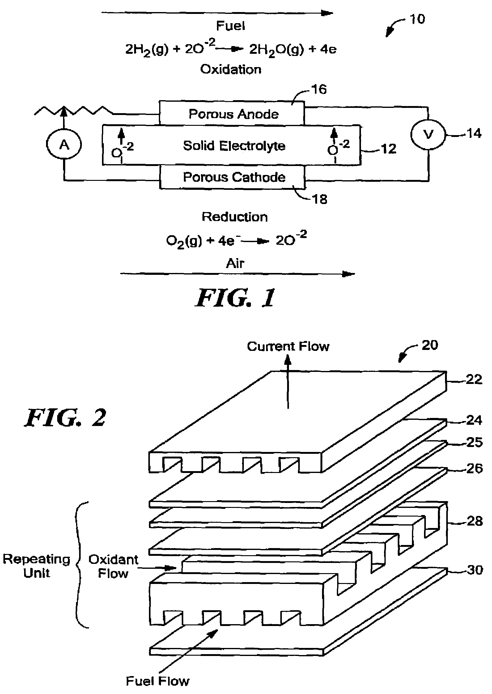
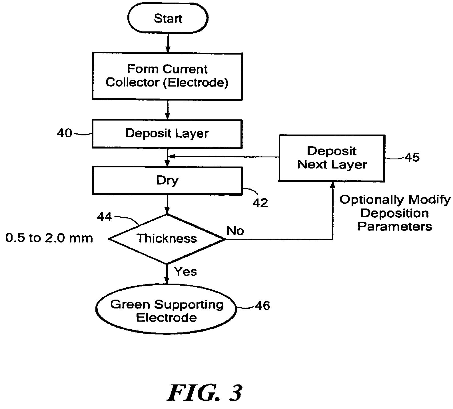
[0021]The present invention provides a method for fabricating a solid oxide fuel cell (SOFC) in a single thermal cycle. This cycle can be performed as a batch or continuous process. An SOFC can be conveniently manufactured according to the invention at a cost that is less than five-hundred dollars per kilowatt of electricity. The manufactured SOFC also operates in a temperature range from about 700 to 1100° C. Similarly, the method of the invention can fabricate an SOFC stack in which several cells are arranged with interconnects separating each cell. Fuel cell devices manufactured by the disclosed method could be used to power, for example, aeronautical systems, computer devices, automotive systems and cellular devices.

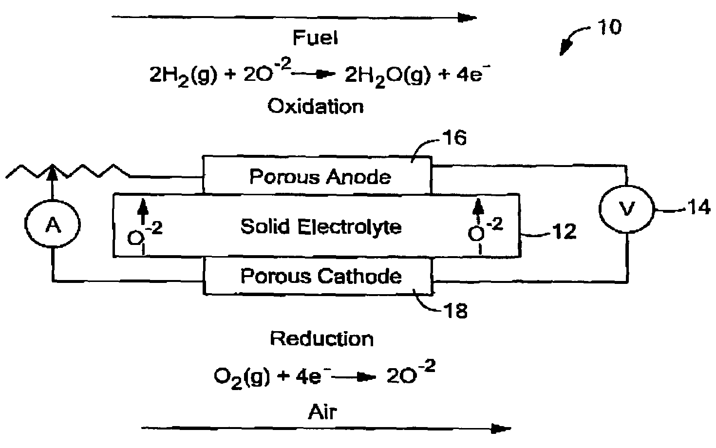
[0022]Fuel cells offer an environmentally clean and versatile power source for efficiently converting fossil fuels into electricity and heat. FIG. 1 is a representation of an SOFC 10 comprising a dense electrolyte 12 that is positioned between porous electrodes, name...


PUM

PropertyMeasurementUnit
thicknessaaaaaaaaaa
temperaturesaaaaaaaaaa
thicknessaaaaaaaaaa

Abstract

The present invention provides a method for conveniently manufacturing a solid oxide fuel cell (SOFC) at a cost that is less than five-hundred dollars per kilowatt of electricity. The method comprises forming an electrode layer and depositing an electrolyte material on the surface of the electrode. The formed structure is an electrode-electrolyte bi-layer. A second electrode is deposited onto this bi-layer to form a multilayer fuel cell structure comprising an electrolyte positioned between two electrodes. This multilayer structure is then heated and fired in a single thermal cycle to remove any binder materials and sinter, respectively, the fuel cell. This thermal cycle can be performed in a furnace having one or more chambers. The chamber(s) preferably contains a variable or multiple frequency microwave source for heating the cell and removing binder materials in the electrolyte and electrode structures. The chamber(s) also preferably include a convection and / or radiation source for sintering the fuel cell. In addition, the method of the invention harmonizes and minimizes the deviation among the thermophysical properties of the electrolyte and electrode structures. This harmonization reduces and minimizes the temperature gradient within the cell such that the structure can be uniformly heated and fired during the thermal cycle. The multilayer structure is also unlikely to distort and fracture by minimizing the temperature gradient in the cell. An SOFC can also be manufactured by the present method in an order of magnitude less time than standard processes.

Description

CROSS REFERENCE TO RELATED APPLICATIONS[0001]This application claims the priority of U.S. Provisional Application No. 60 / 501,742 filed Sep. 10, 2003 and entitled, SINGLE STEP CO-FIRING PROCESS FOR FUEL CELL MANUFACTURE, which is hereby incorporated by reference herein.BACKGROUND OF THE INVENTION[0002]A fuel cell is a device or system that generates electricity by an electrochemical reaction in which oxygen and hydrogen combine to form water. An electrolyte in the cell carries charged particles across a cathode to an anode. Catalysts are often employed to accelerate and improve the efficiency of the electrochemical reaction. Fuel cell devices are a viable source of alternative energy. These devices are generally more efficient and produce less pollution than conventional sources of power. The electricity produced by fuel cells can be used to power, for example, aeronautical systems, computer devices, automotive systems and cellular devices.[0003]Typically, fuel cells are classified b...

Claims


Application Information

Patent Timeline
Patent Type & Authority Patents(United States)
IPC IPC(8): H01M8/10C04B35/64H01MH01M4/86H01M4/88H01M4/90H01M8/12
CPCH01M4/9066H01M8/1213H01M8/1246H01M4/8621H01M4/8657H01M4/8885H01M4/9016H01M4/9033H01M2300/0074H01M2300/0077H01M2300/0094Y02E60/521Y02E60/525Y02E60/50Y02P70/50H01M8/00H01M4/86H01M8/12
Inventor SECCOMBE, JR., DONALD A.ORBECK, GARYGOPALAN, SRIKANTHPAL, UDAY
Owner TRUSTEES OF BOSTON UNIV
Why Eureka
Try Eureka