Apparatus and method for leak testing

a technology of apparatus and leakage detection, applied in the direction of measuring devices, instruments, structural/machine measurement, etc., can solve problems such as pressure changes, and achieve the effect of more surely measuring

Active Publication Date: 2010-08-19
FUKUDA CO LTD
View PDF19 Cites 11 Cited by
  • Summary
  • Abstract
  • Description
  • Claims
  • Application Information

AI Technical Summary

Benefits of technology

[0025]Preferably, a plurality of fins are disposed in an outer periphery of the measuring device body, the fins arranged spacedly in a longitudinal direction of the measuring device body. In this arrangement, the fins are arranged in a distributed manner in the longitudinal direction of the measuring device body. This enables the heat to be caught from a wide area of the inner space, thereby enabling the average temperature of the inner space to be more surely measured.

Problems solved by technology

Such a temperature change also causes a pressure change.

Method used


Image

  • Apparatus and method for leak testing
  • Apparatus and method for leak testing
  • Apparatus and method for leak testing

Examples


first embodiment

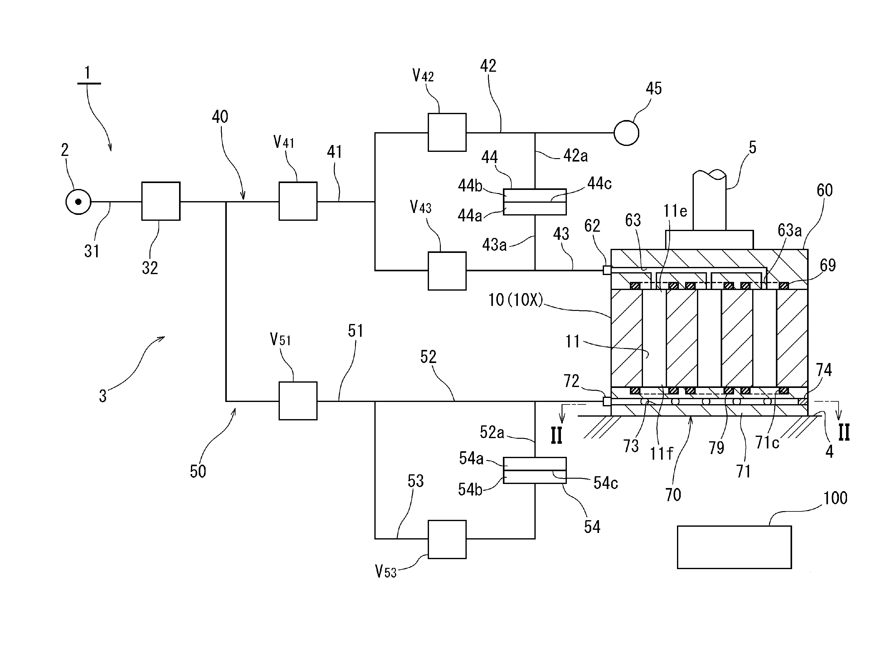
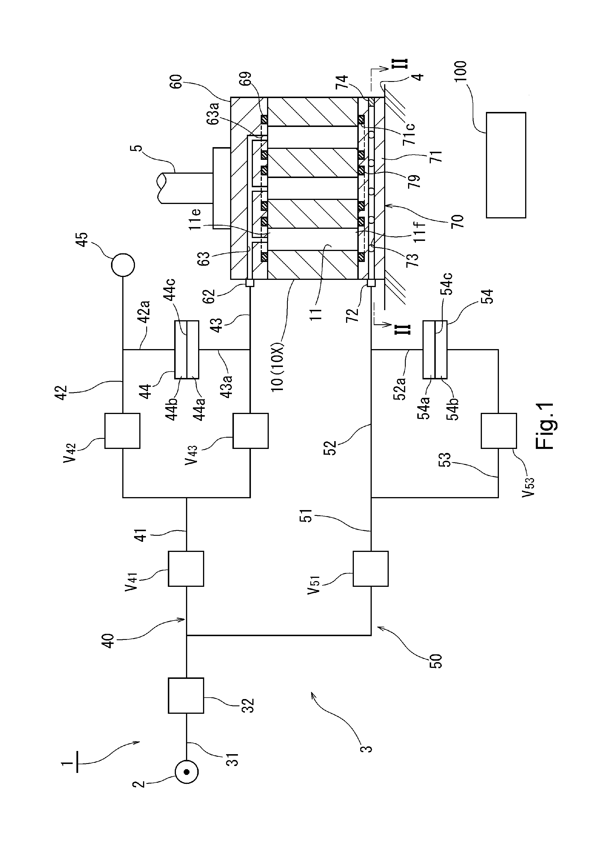
[0034]FIG. 1 schematically illustrates a circuit configuration of a leak testing apparatus 1 according to the present invention. A test object of the leak testing apparatus 1 is a workpiece 10. An example of the workpiece 10 is a cylinder block of an automotive engine. A plurality of inner spaces 11 are formed inside the workpiece 10. In this embodiment, all of the inner spaces 11 are open to an upper outer surface and a lower outer surface of the workpiece 10.

[0035]As shown in FIG. 1, the leak testing apparatus 1 has a pressurized gas source 2 and a pressurized gas passage 3. The pressurized gas source 2 is an air compressor. The pressurized gas source 2 can produce an air pressure in the order of some hundreds of kPa.

[0036]The pressurized gas passage 3 is constructed as follows:

[0037]A common passage 31 of the pressurized gas passage 3 extends from the pressurized gas source 2. A regulator 32 is provided in the common passage 31. The regulator 32 controls pressure in a portion of ...

second embodiment

[0086]For example, in a second embodiment shown in FIG. 3, an inner space 11A of the plurality of inner spaces 11 extends from an upper surface of the workpiece 10 but doesn't reach a lower surface of the workpiece 10. A lower end portion of the inner space 11A is distanced from the heat sensitive member 70. Therefore, it takes time for temperature change inside the inner space 11A to be transmitted to the heat sensitive member 70. On the other hand, the inner space 11A is located near one side surface 10a (surface in the right side in FIG. 3) of the workpiece 10.

[0087]Now, a temperature measuring device 80 is placed on the side surface 10a of the workpiece 10. The temperature measuring device 80 assists the heat sensitive member 70 in detecting temperature. The temperature measuring device 80 is a resistance thermometer. Although not shown in detail, a temperature measuring circuit is integrated in the temperature measuring device 80. The temperature measuring circuit has two (a pl...

third embodiment

[0094]In a third embodiment shown in FIG. 5, a pressure control valve V40 is disposed in the first introduction passage 40. Air pressure in the first introduction passage 40 can be controlled by the pressure control valve V40 and, consequently, introduction pressure to the inner spaces 11 can be controlled. A pressure control valve V50 is disposed in the second introduction passage 50. Air pressure in the second introduction passage 50 can be controlled by the pressure control valve V50 and, consequently, pressure inside the pressure chamber 73 can be controlled.

[0095]By the pressure control valves V40, V50, the inner pressure of the pressure chamber 73 and the inner pressure of the inner spaces 11 are controlled such that the inner pressure of the pressure chamber 73 is greater than the inner pressure of the inner spaces 11. For example, the inner pressure of the inner spaces 11 is controlled at 300 kPa and the inner pressure of the pressure chamber 73 is controlled at 500 kPa. In ...


PUM


Abstract

A leak testing apparatus is provided by which temperature change can be surely detected even when an inner space of a workpiece is narrow.
A body 71 of a heat sensitive member 70, made of a material having high thermal conductivity, is abutted against an outer surface of a workpiece 10 to close an opening of an inner space 11 of the workpiece 10. A pressure chamber 73 is formed inside the body 71 as arranged along the outer surface and as arranged over an area wider than the opening. Pressurized gas is introduced to the pressure chamber 73. Data on pressure change in the inner space 11 of the workpiece 10 is compensated based on inner pressure information regarding the pressure chamber 73, and leak judgment is made.

Description

TECHNICAL FIELD[0001]This invention relates to an apparatus and a method for leak testing by introducing pressurized gas into an inner space of a workpiece and measuring pressure change in the inner space.BACKGROUND ART[0002]In general, in a differential pressure type leak test, pressurized gas such as compressed air is introduced to an inner space of a workpiece and a reference space. Then the inner space and the reference space are blocked from each other, each forming a closed system. If there is leak in the workpiece, the leak is detected as a differential pressure. In this way, a pass / fail judgment can be made on the workpiece.[0003]When the pressurized gas is introduced into the inner space of the workpiece, the temperature of the inner space is increased due to adiabatic compression. Then, the heat is released with time, and the temperature is decreased. If there is temperature difference between the workpiece and facilities surrounding the workpiece or ambient air due to hea...

Claims


Application Information

Patent Timeline
Patent Type & Authority Applications(United States)
IPC IPC(8): G01M3/20
CPCG01M3/3263
Inventor SASAKI, TORU
Owner FUKUDA CO LTD
Why Eureka
Try Eureka