Cooling device and construction machine or working machine equipped with the same

a cooling device and construction machine technology, applied in the direction of liquid fuel engines, semiconductor/solid-state device details, lighting and heating apparatus, etc., can solve the problem of increased noise, achieve high-silent operation, enhance cooling efficiency, and reduce operation noise

Active Publication Date: 2010-08-19
KOMATSU LTD
View PDF12 Cites 12 Cited by
  • Summary
  • Abstract
  • Description
  • Claims
  • Application Information

AI Technical Summary

Benefits of technology

[0012]In the cooling device according to the aspect of the invention, the angle between the line connecting the air-flow-direction downstream side end of the inner circumferential wall to the air-flow-direction downstream side end of the outer circumferential wall and the line orthogonal to the air flow direction is 9 degrees or more and 45 degrees or less. With this arrangement, when the cooling fan is rotated and an air flow is generated, negative pressure generated within a space provided between the inner circumferential wall and outer circumferential wall of the ring suctions the air, or the suctioned air is swept from the space. Accordingly, the flow of air blown by the cooling fan is increased. Thus, cooling capability is enhanced even when the rotation speed of the cooling fan is the same as conventional. Even when the rotation speed of the cooling fan is reduced, the same cooling capability can be obtained and the noise can be reduced.
[0028]In the cooling device according to the aspect of the invention, the flow of air blown by the cooling fan can be sufficiently increased without increasing the rotation speed of the cooling fan.

Problems solved by technology

However, when the rotation speed of the cooling fan is increased, noise is increased.

Method used


Image

  • Cooling device and construction machine or working machine equipped with the same
  • Cooling device and construction machine or working machine equipped with the same
  • Cooling device and construction machine or working machine equipped with the same

Examples


first exemplary embodiment

Entire Arrangement of Hydraulic Excavator 1

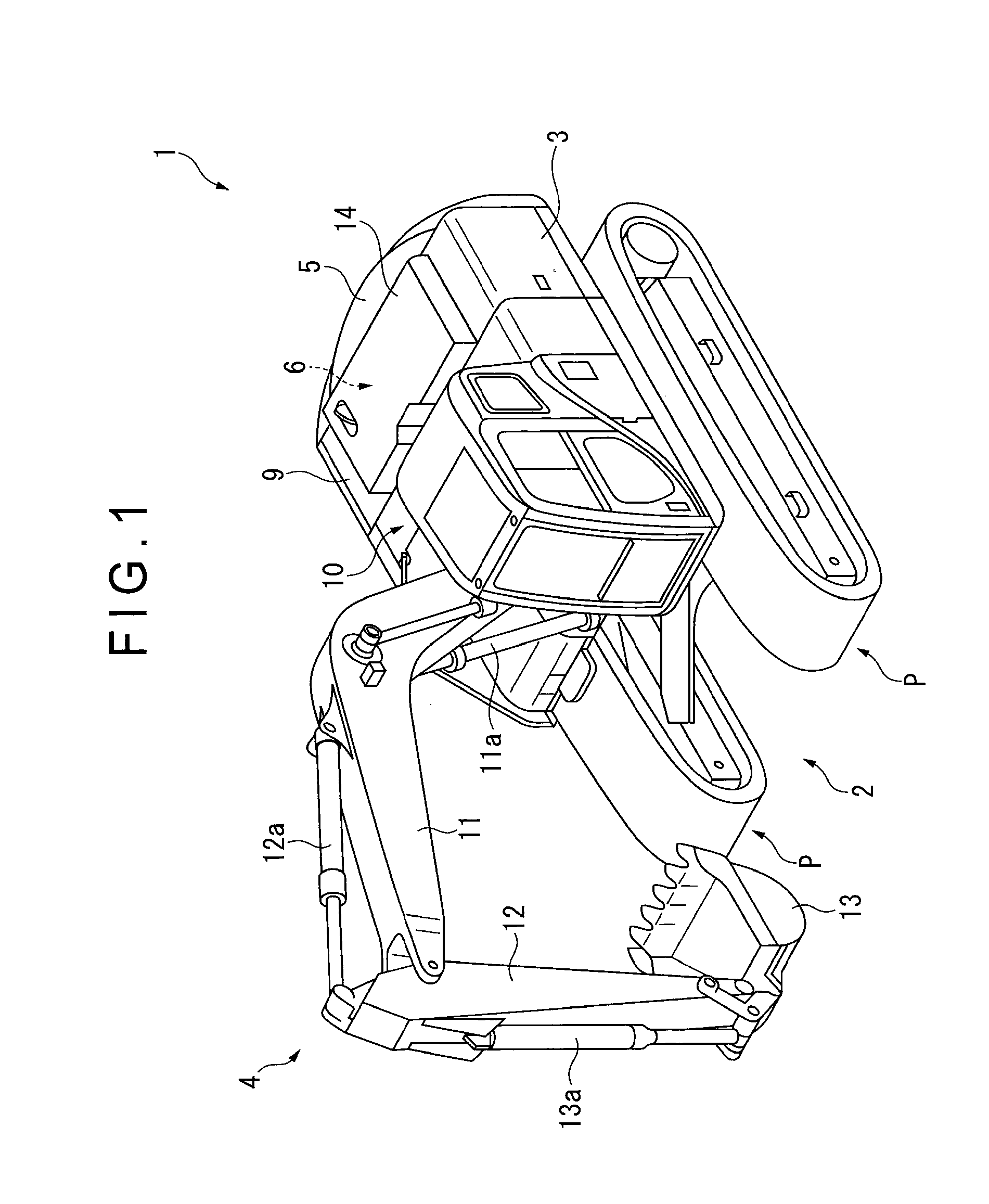
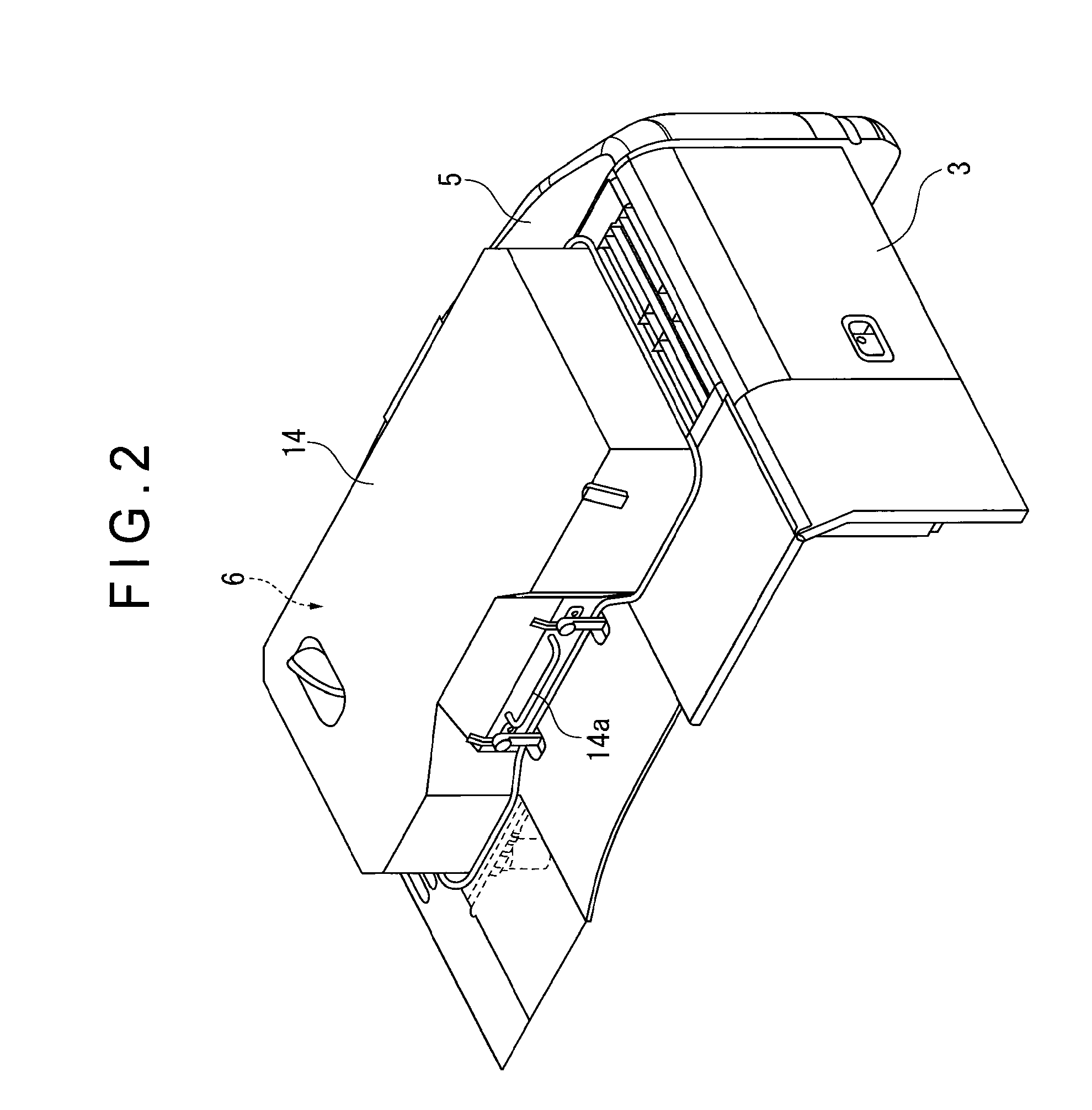
[0050]As shown in FIG. 1, a hydraulic excavator 1 according to a first exemplary embodiment includes: an undercarriage 2; a swing frame 3; a working equipment 4; a counterweight 5; an engine room 6; an equipment enclosure 9; a cab 10; and a cooling unit 20 (see FIG. 3).

[0051]The undercarriage 2 moves the hydraulic excavator 1 forward and backward by rotating crawler belts P wound around right and left ends in the traveling direction while carrying the swing frame 3 in a manner swingable on an upper surface of the undercarriage 2.

[0052]The swing frame 3 is swingable in any direction on the undercarriage 2. The working equipment 4, counterweight 5, engine room 6 and cab 10 are provided on an upper surface of the swing frame 3.

[0053]The working equipment 4 includes: a boom 11; an arm 12 provided on an end of the boom 11; and a bucket 13 provided on an end of the arm 12. The working equipment 4 is used to excavate gravel and sand at a site of c...

second exemplary embodiment

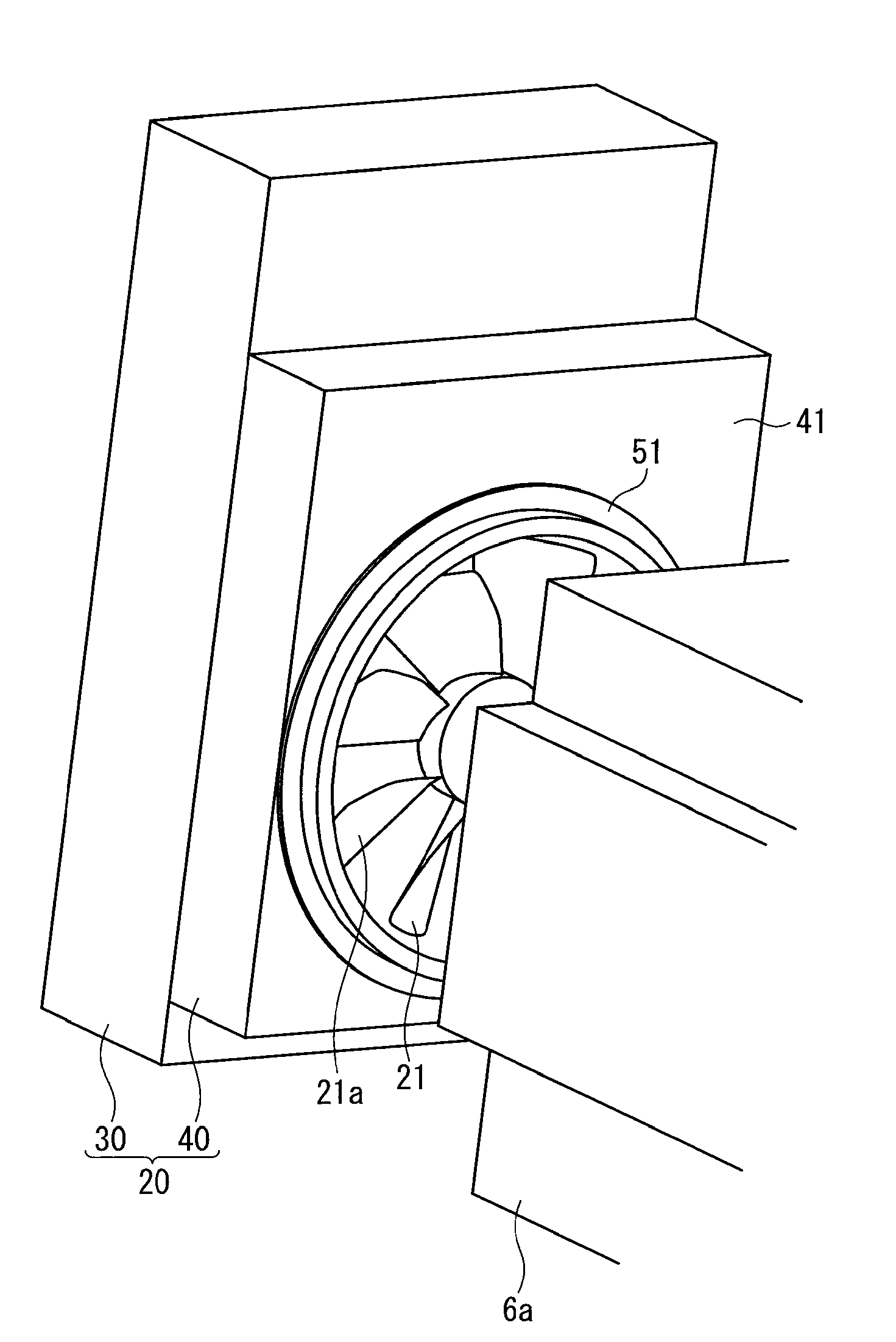
[0100]In the first exemplary embodiment, the inner circumferential wall and the outer circumferential wall are provided as the annular ring 51 surrounding the cooling fan 21.

[0101]In the cooling device according to the second exemplary embodiment, a plurality of wall components 112 are provided as shown in FIG. 12, in place of the consecutive ring 51. More specifically, the wall components 112 are combined around the rotation shaft of the cooling fan 21 to surround the cooling fan 21, which is different from the first exemplary embodiment.

[0102]As shown in FIG. 8 according to the first exemplary embodiment, the wall components 112 respectively include the inner circumferential wall 52 and the outer circumferential wall 53, and the air-flow-direction downstream side end of the cooling fan 21 is positioned at a further downstream position in the air flow direction than the air-flow-direction downstream side end of the inner circumferential wall 52.

[0103]The interior covering ratio is ...


PUM


Abstract

A cooling device includes: a cooling fan; a shroud provided at an outer circumferential side of the cooling fan; an inner circumferential wall provided on the shroud and adjacent to the outer circumference of the cooling fan; and an outer circumferential wall provided to surround the inner circumferential wall. An air-flow-direction downstream side end of an outer circumferential edge of the cooling fan is positioned at a further downstream position in an air flow direction than an air-flow-direction downstream side end of the inner circumferential wall. An angle between: an line connecting the air-flow-direction downstream side end of the inner circumferential wall to the air-flow-direction downstream side end of the outer circumferential wall in cross section along the air flow direction of the inner circumferential wall and the outer circumferential wall; and a line orthogonal to the air flow direction, is 9 degrees or more and 45 degrees or less.

Description

TECHNICAL FIELD[0001]The present invention relates to a cooling device and a construction machine or work machine including the same. More particularly, the present invention relates to a cooling device including a cooling fan and a shroud surrounding the cooling fan, and a construction machine or work machine including the same.BACKGROUND ART[0002]Traditionally, a cooling system of an engine installed in a construction machine mainly includes a radiator and a cooling fan. The radiator circulates cooling medium between the radiator and the engine and cools the cooling medium by outer air. The cooling fan forms air flow around the radiator and aids heat exchange of the radiator. Further, a shroud is provided between the radiator and the cooling fan to surround the radiator and the cooling fan for ensuring air flow from the radiator to the cooling fan (for example, see Patent Document 1).[0003]In recent years, the total heat quantity of an engine is increased and therefore the water t...

Claims


Application Information

Patent Timeline
Patent Type & Authority Applications(United States)
IPC IPC(8): F28F13/00
CPCB60K11/04E02F9/00E02F9/0866F01P11/10F04D29/164
Inventor YABE, MITSUOSHINODA, HIROKIIKEDA, MASAHIROWATANABE, TOMOYAKAWANO, ATSUSHIFUCHITA, SEIICHIKUSUYAMA, YASUHIROMATSUKI, TERUYUKI
Owner KOMATSU LTD
Why Eureka
Try Eureka