In-well rigless esp

a technology of electrical submersible pumps and rigs, which is applied in the direction of fluid removal, borehole/well accessories, sealing/packing, etc., can solve the problems of environmental damage, critical and expensive resources of rigs in subsea or remote applications, etc., and achieves cost-effectiveness, reduce the overall cost of installation, and reduce the diameter of tubing strings

Active Publication Date: 2010-08-19
BAKER HUGHES INC
View PDF6 Cites 47 Cited by
  • Summary
  • Abstract
  • Description
  • Claims
  • Application Information

AI Technical Summary

Benefits of technology

[0008]A tubing hanger is attached to the top of the tubing string that lands in a wellhead to support the string of tubing. An electrical penetrator on the tubing hanger is used to route the power cable and hydraulic lines adjacent and external to the tubing string. The penetrator allows passage of the required cables and lines while preventing communication of the seawater from entering the well or well fluid from being in communication with the environment. For existing wells where space may prevent the penetrator from passing through the hanger, a swage can be connected to the top of the well casing to provide the necessary space to use a larger tubing hanger that would allow the penetrator to pass through the hanger without the need to reduce the diameter of the tubing string.
[0009]The invention is simple and allows for cost-effective ESP installation and retrieval via a wireline or coiled tubing. This invention further advantageously allows for environmentally friendly retrieval of an ESP system by cleaning the ESP prior to retrieval from the well. This invention could help operators decrease the overall cost of installation and retrieval of ESP systems.

Problems solved by technology

However, the rig is a critical and expensive resource in subsea or remote applications.
In addition, retrieval of the ESP can be environmentally harmful because formation fluid can contaminate the environment.

Method used


Image

  • In-well rigless esp
  • In-well rigless esp
  • In-well rigless esp

Examples


Embodiment Construction

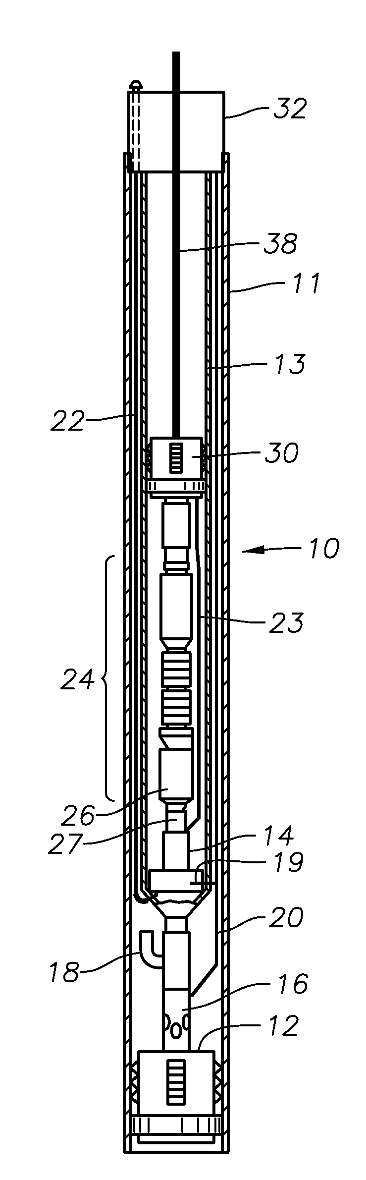
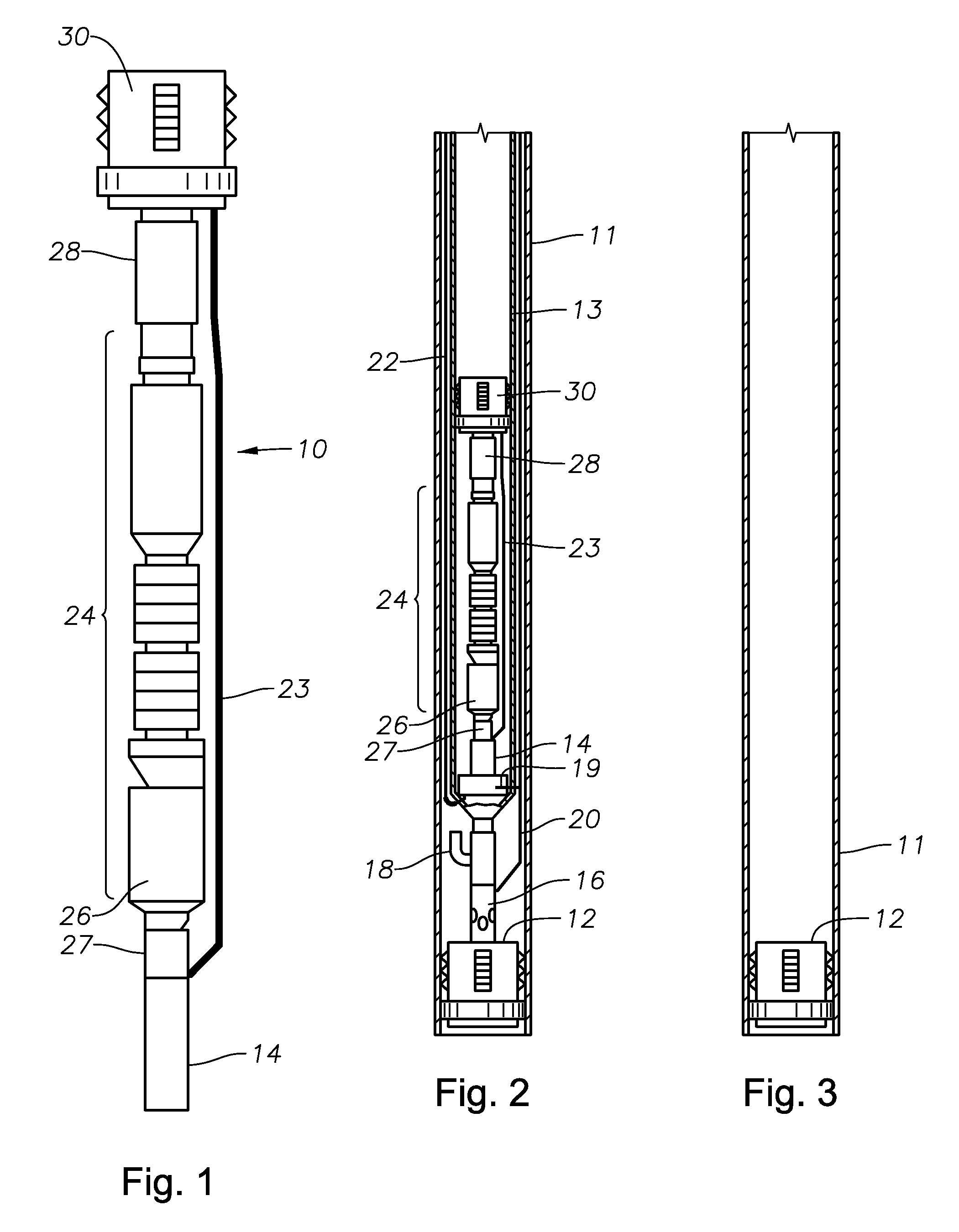
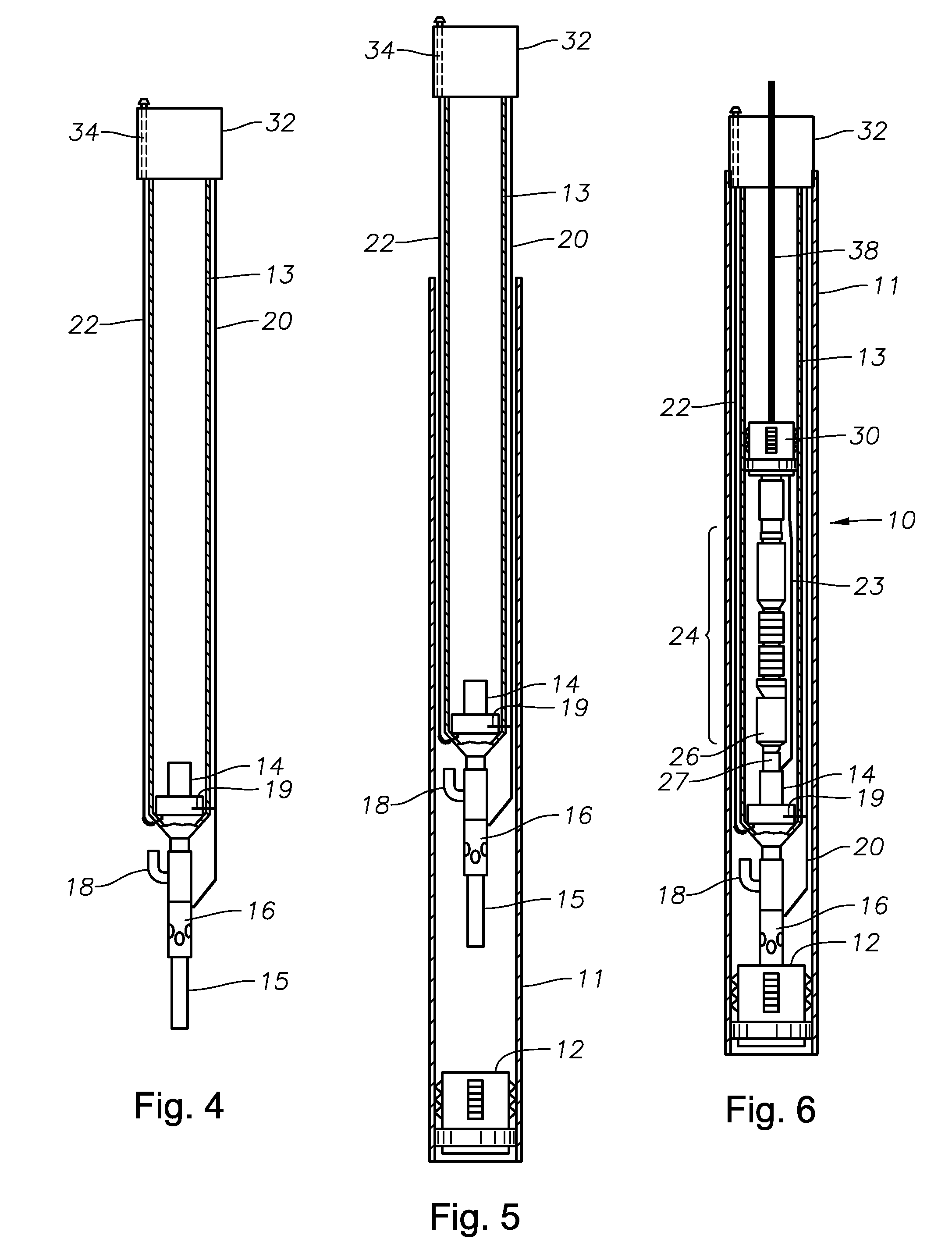
[0022]Referring to FIGS. 1 and 2, an embodiment of an in-well rigless ESP system 10 is shown outside and inside a tubing string 13 and a casing 11, respectively. The in-well rigless ESP system 10 includes a wet connector 14 that connects a hydraulic control line 19 to set a hydraulic packer 30, and also connects a power cable 22 to power a motor 26 of the ESP 24. The wet connector 14 is located in a tubular assembly. The tubular assembly is rigidly attached to the lower end of the tubing string 13. The wet connector 14 allows the power cable 22 and control line 20 coming from the surface to provide power to the ESP 24 and hydraulic control to the packer 30. A stinger 27 approximately at the base of the ESP system 10 has electrical conductors that mate with electrical conductors in the wet connector and hydraulic ports that mate with hydraulic ports in the wet connector. The packer 30 will seal the discharge of the ESP 24, which is driven by the motor 26 located at its base. An expan...


PUM


Abstract

An in-well ESP string that can be installed or retrieved with a wireline instead of a rig. The ESP is combined with a motor and a hydraulic valve to pump formation fluid from a well to the surface. A wet connector is used to facilitate electrical and hydraulic connections. The ESP system is disposed within a tubing string located within the casing of a well. The hydraulic valve controls the flow of formation fluid to the ESP, opening to allow formation fluid to flow to the ESP, and closing to shut off production. When the valve is closed, the ESP may be cleaned with brine introduced via a flow port in the valve. This cleaning operation allows the ESP string to be to retrieved in an environmentally friendly manner. In addition, the wireline installation and retrieval is significantly less costly and less complicated than currently possible with a rig.

Description

CROSS-REFERENCE TO RELATED APPLICATION [0001]This application claims priority to provisional application 61 / 153,376 filed Feb. 18, 2009.FIELD OF THE INVENTION [0002]This invention relates in general to installation and retrieval of electrical submersible pumps (ESPs), and in particular to a string for the installation and retrieval of ESP equipment without a rig.BACKGROUND OF THE INVENTION[0003]ESP's are used in wells to pump formation fluids, such as oil, up to the surface via production tubing. Generally a rig is required to install and retrieve an ESP and its components down and out of the well. Once in place the ESP system controls the production of fluid to the surface.[0004]It is desirable to install and remove ESP systems in a cost-effective, simplified, and environmentally friendly manner. However, the rig is a critical and expensive resource in subsea or remote applications. In addition, retrieval of the ESP can be environmentally harmful because formation fluid can contami...

Claims


Application Information

Patent Timeline
Patent Type & Authority Applications(United States)
IPC IPC(8): E21B43/00
CPCE21B43/128E21B23/14
Inventor MARTINEZ, IGNACIO
Owner BAKER HUGHES INC
Why Eureka
Try Eureka