Constant strain spring compensation device

a compensation device and constant strain technology, applied in the direction of power supply lines, thin material processing, vehicle components, etc., can solve the problems of urgent reliability of overhead contact lines, reduce pantograph and overhead contact lines faults, and constant strain of overhead contact lines

Inactive Publication Date: 2010-08-19
TIE RONGJUN +4
View PDF5 Cites 10 Cited by
  • Summary
  • Abstract
  • Description
  • Claims
  • Application Information

AI Technical Summary

Benefits of technology

[0012]The constant strain spring compensation device is an important component of the overhead contact lines of electrified railway. It is an important device to maintain a constant strain of the overhead contact lines despite the variation of the temperature. The capability of the constant strain spring compensation device directly affects the suspension elasticity of the overhead contact lines and the standard status of the overhead contact lines in spatial position etc., which is greatly significant for reducing the faults of the pantograph and overhead contact lines and improving safety reliability of the overhead contact lines.
[0013]The object of the present invention is to provide a device automatically compensating the lengt

Problems solved by technology

How to ensure the safety, reliability thereo

Method used


Image

  • Constant strain spring compensation device
  • Constant strain spring compensation device
  • Constant strain spring compensation device

Examples


Embodiment Construction

[0060]The constant strain spring compensation device of the present invention will be further described below with reference to the accompanying drawings and embodiments.

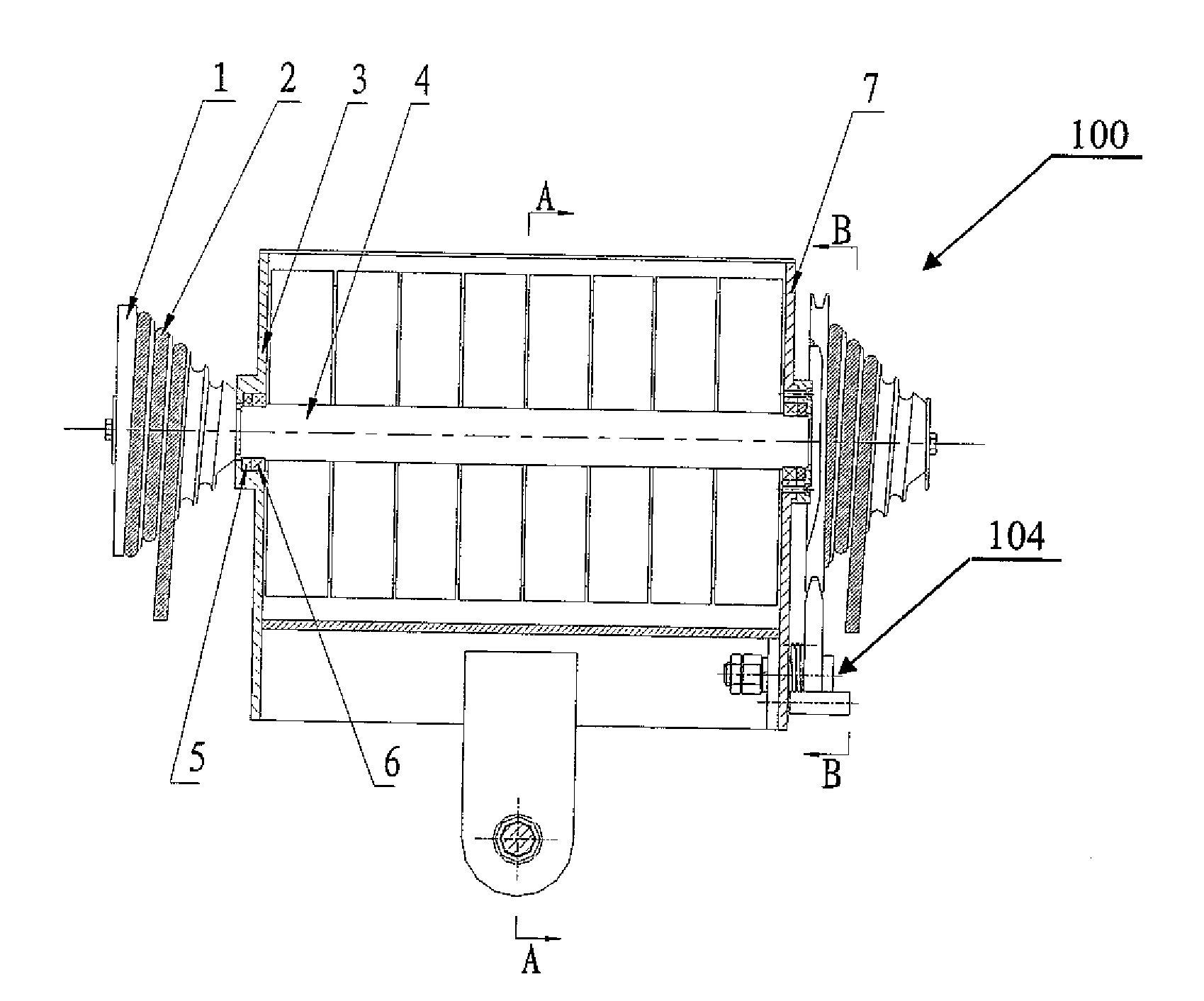
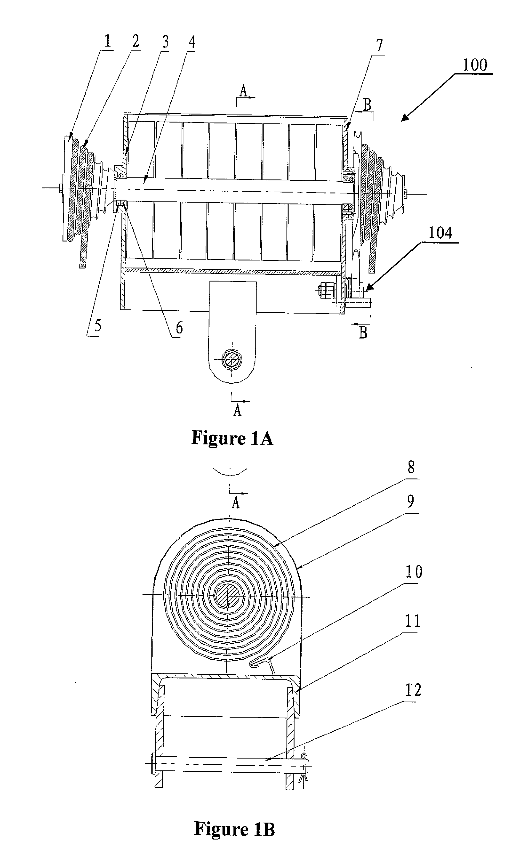
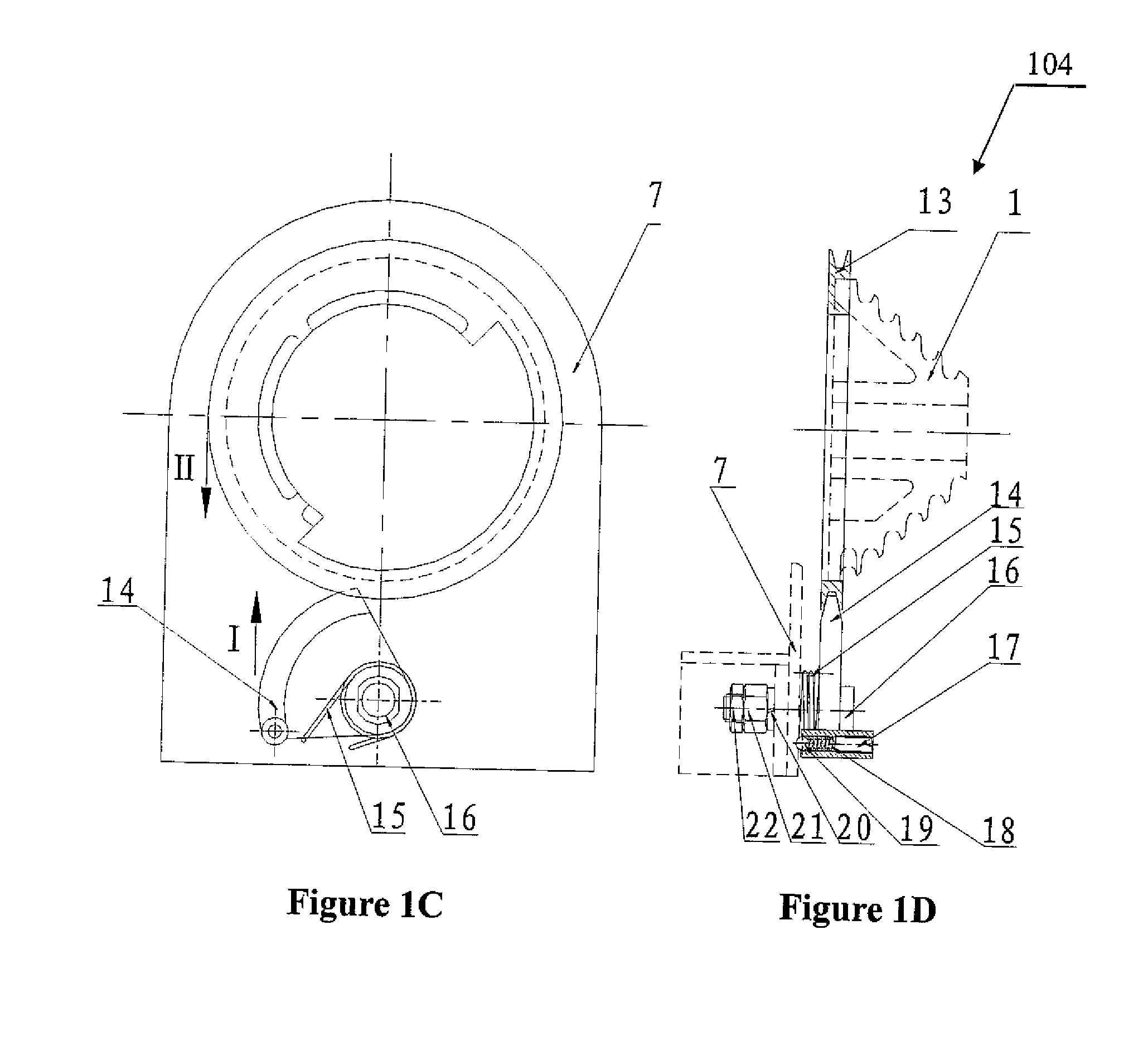
[0061]The structural diagrams of the constant strain spring compensation device 100 of the present invention are schematically shown in FIGS. 1A and 1B. The constant strain spring compensation device 100 mainly comprises the involute grooved pulley 1, compensation cable 2, left end-plate 3, spindle 4, oil seal 5, bearing 6, right end-plate 7, contact flat spiral spring 8, housing 9, fastening angle steel 10, mounting base 11, pin 12, and wire-breaking arresting device 104, etc.

[0062]The contact flat spiral spring 8 in the illustrated embodiment is a variable torque flat spiral spring. The end-radius of the involute grooved pulley can be determined by the following equation: End-radius=Start radius×(End torque of the flat spiral spring / Start torque of the flat spiral spring).

[0063]Wherein the left end-plate 3, right ...


PUM


Abstract

A constant strain spring compensation device, mainly comprising the grooved pulley, compensation cable, left end plate, spindle, oil seal, bearing, right end plate, contact flat spiral spring, housing, fastening angle steel, mounting base, pin, and wire-breaking arresting device. Said grooved pulley is fixed on the spindle, said compensation cable is wound and one of its ends is fixed on the grooved pulley, and the other end is connected to exterior overhead contact lines. Said spindle is supported on left end plate and right end plate by using the oil seal and bearing. Said left end plate, right end plate, housing, fastening angle steel, and mounting base form a closed box base. Said pin is connected to the side of the mounting base remote from said box base. Said contact flat spiral spring is arranged within said box base with the inner end hook being connected to the spindle and the outer end hook being connected to the fastening angle steel of the box base. The constant strain spring compensation device of the present invention is compact, small in size and weight. It may maintain a certain strain on the overhead contact lines of electrified railway to reduce the contact loss rate of its pantograph.

Description

FIELD OF THE INVENTION[0001]The present invention relates to the filed of electrical power supply for overhead contact lines of electrified railway, particularly relates to a constant strain spring compensation device which can maintain a certain strain on the overhead contact lines (catenary cables, contact cables and flexible catenary spans) of electrified railway to reduce the contact loss rate of its pantograph.BACKGROUND OF THE INVENTION[0002]The overhead contact lines (catenary cables, contact cables and flexible catenary spans) of electrified railway would affect both the height and strain of the contact suspension due to the shrinkage or expansion caused by variation in temperature, besides, also because of the elongation of elastic linear material caused by creep, wear of cable, etc., as well as the tilting of the supports due to long time use. These factors cause the contact loss, and deteriorate the current-collecting capability of overhead contact lines, whilst increased...

Claims


Application Information

Patent Timeline
IPC IPC(8): B60M1/26
CPCB60M1/26B60M1/02
Inventor TIE, RONGJUNWU, LIQUNTIE, RONGKANG
Owner TIE RONGJUN
Why Eureka
Try Eureka