
Method and circuit arrangement for the feedback of commutation energy in three-phase current drive systems with a current intermediate circuit converter

a technology of commutation energy and three-phase motors, applied in the direction of electronic commutators, synchronous motor starters, efficient power electronics conversion, etc., can solve the problem of using phase sequence inverters and achieve the effect of removing this disadvantag

Inactive Publication Date: 2010-08-19
ECONODRIVES
View PDF2 Cites 4 Cited by
  • Summary
  • Abstract
  • Description
  • Claims
  • Application Information

AI Technical Summary

Benefits of technology

[0005]It is an object of the present invention to eliminate this disadvantage by a cost-effective solution.

Problems solved by technology

It is therefore very problematic to use a phase sequence inverter for driving different motors having different leakage inductances.

Method used


Image

  • Method and circuit arrangement for the feedback of commutation energy in three-phase current drive systems with a current intermediate circuit converter
  • Method and circuit arrangement for the feedback of commutation energy in three-phase current drive systems with a current intermediate circuit converter
  • Method and circuit arrangement for the feedback of commutation energy in three-phase current drive systems with a current intermediate circuit converter

Examples


Embodiment Construction

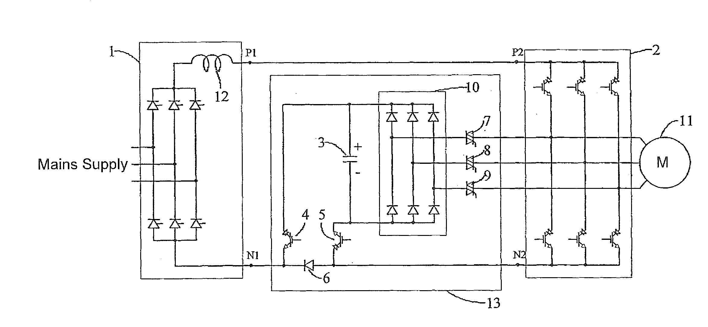
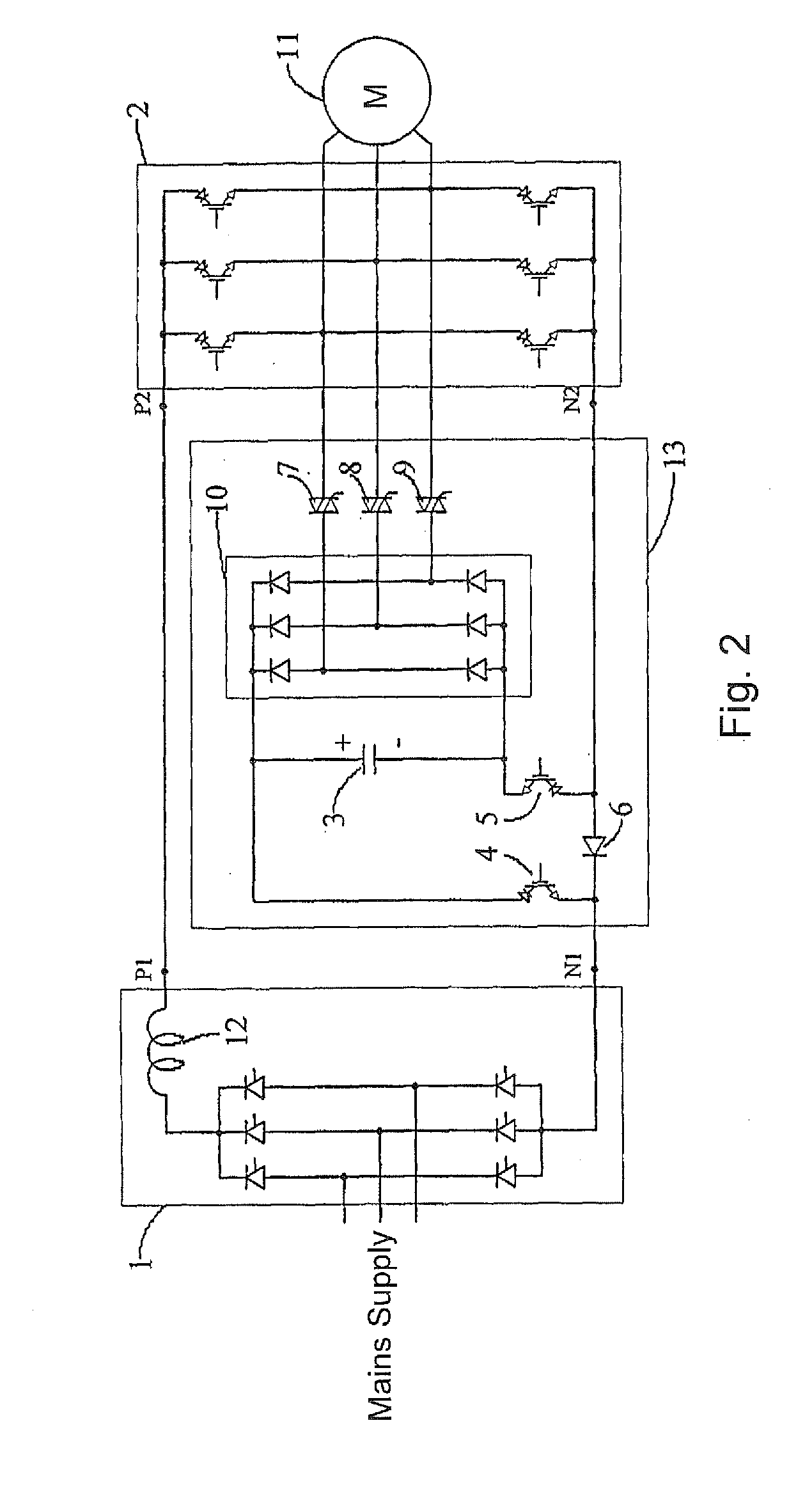
[0015]FIG. 2 shows a typical circuit for implementing the method described in claim 1.

[0016]The depicted RIGBT components, 4 and 5 symbolize a reverse blocking component that is switchable on and off by the gate electrode. According to the state of the art, this component is either[0017]a reverse blocking IGBT (RIGBT) or[0018]an IGBT with a series connected diode, or[0019]a GTO thyristor.

[0020]Structure of the circuit according to FIG. 2:

[0021]Current source 1 and inverter 2:

[0022]Current source 1 is formed by a line-commutated rectifier connected to the AC network together with intermediate circuit inductor 12. Positive power source terminal P1 is connected to positive inverter terminal P2, and three-phase motor 11 is connected to the outputs on the motor side of inverter 2. The inverter 2 comprises no commutation capacitors.

[0023]Commutation unit 13:

[0024]The three motor side outputs of inverter 2 are connected to the three middle connections of diode bridge 10 by respective triac...


PUM


Abstract

There is disclosed a method and a circuit arrangement for the feedback of commutation energy in three-phase current drive systems with a current intermediate circuit converter. Commutation energy is released at each commutation in the inverter. The commutation unit ensures that the released energy is directly fed back to the current intermediate circuit in two steps. In the first step, the commutation energy is fed into the commutation capacitor by a rectifier circuit (diode bridge and three triacs). In the second step, the commutation energy is fed directly from the commutation capacitor into the current intermediate circuit by means of three semiconductors (first RIGBT, second RIGBT, diode) so that the current of the intermediate circuit flows through the capacitor over a controlled period of time.

Description

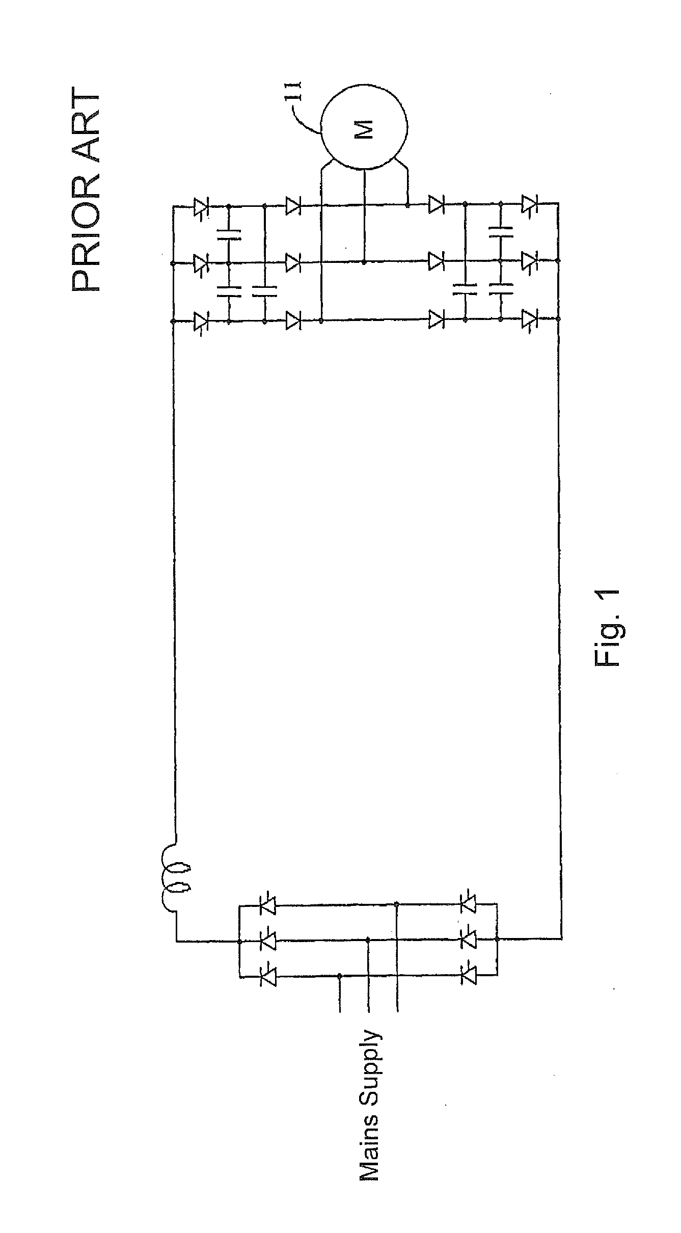
CROSS REFERENCE TO RELATED APPLICATIONS[0001]The present application is a 35 U.S.C. §371 National Phase conversion of PCT / CH2006 / 000565, filed Oct. 6, 2006, the disclosure of which is incorporated herein by reference. The PCT International Application was published in the German language.FIELD OF THE INVENTION[0002]The invention relates to a method and a circuit arrangement for the feedback of the commutation energy in three-phase motor drive systems with a current intermediate circuit converter.BACKGROUND OF THE INVENTION[0003]Today, in practical applications for current intermediate circuit converters, the so-called phase sequence inverter (K. P. Philips, “Current Source Converter for AC Motor Drives,” IEEE Trans. Ind. Appl., Vol. IA-8, pp. 679-683, November / December 1972) is almost invariably used, FIG. 1.[0004]In a phase sequence inverter, the commutation capacitors are adapted to the leakage inductance of the motor being used. It is therefore very problematic to use a phase seq...

Claims


Application Information

Patent Timeline
IPC IPC(8): H02P6/14
CPCH02M1/34H02M7/5387Y02B70/1491H02P27/06H02M2001/342Y02B70/10H02M1/342
Inventor KANYO, PAL
Owner ECONODRIVES
Learn More