
Energy management

a technology of energy management and energy supply, applied in non-electric variable control, process and machine control, instruments, etc., can solve the problems of high cost of energy production, increased cost of power generation or supply, and increased cost at additional generation levels

Inactive Publication Date: 2010-08-19
GENERAL ELECTRIC CO
View PDF100 Cites 71 Cited by
  • Summary
  • Abstract
  • Description
  • Claims
  • Application Information

AI Technical Summary

Benefits of technology

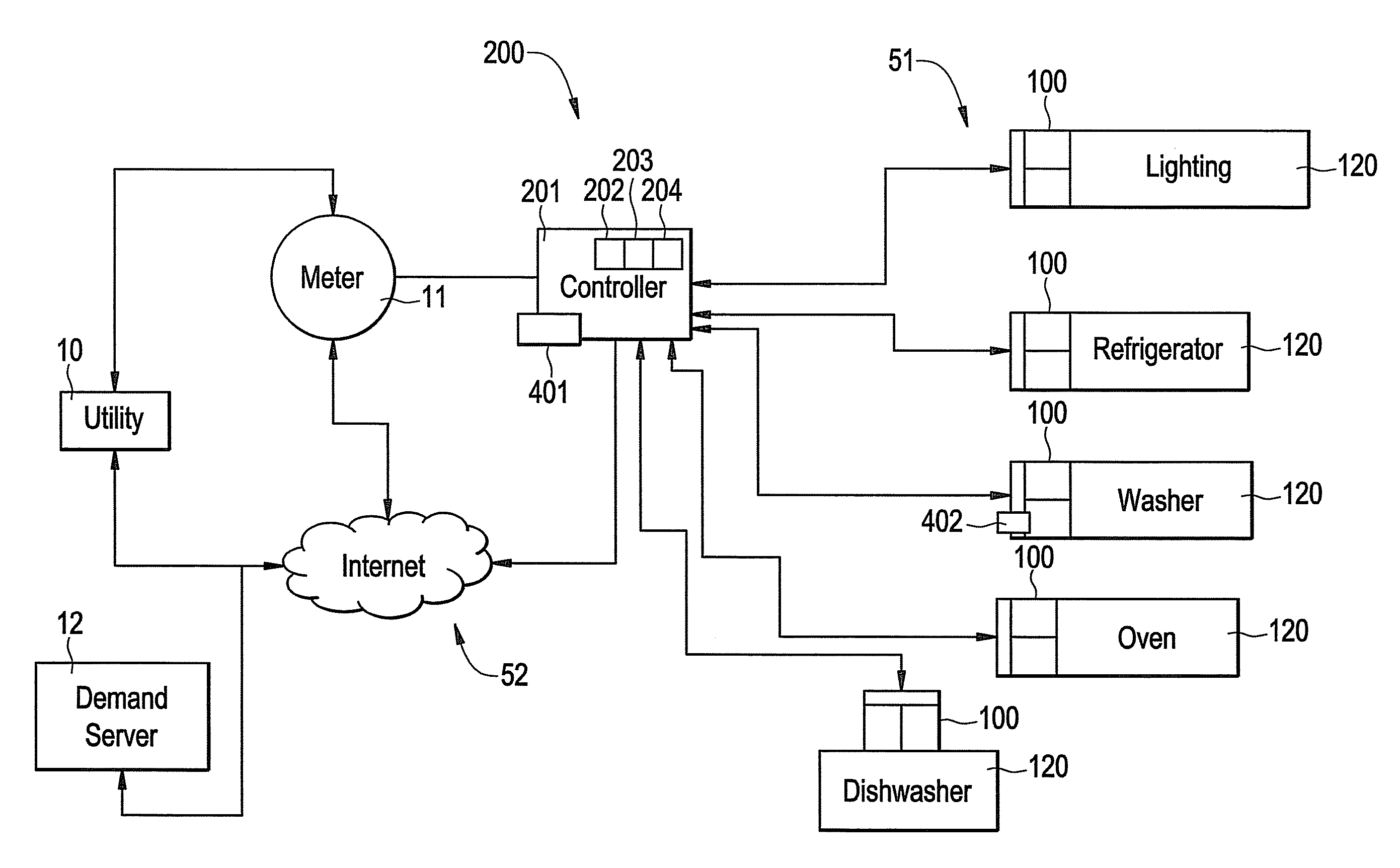
[0027]An embodiment further incorporates a counter or timer 106 so that when light is detected for a predefined period the energy consuming device is placed in an energy saving operational mode. To improve operation, the module 100 can include a module main controller 111 that includes logic circuitry that receives a signal from the light sensor 105 and is connected to the counter or timer 106 so that the module main controller triggers an energy saving operational mode of the energy consuming device when detected light exceeds a predefined level for a predefined period of time. For example, the energy saving or reduced operational mode could start three hours after it is determined morning starts and be maintained until twelve hours after morning starts. The counter 106 also allows the module 100 to know that the room has been dark for a predetermined number of hours so that normal operation of the energy consuming device 120 can be restored.

Problems solved by technology

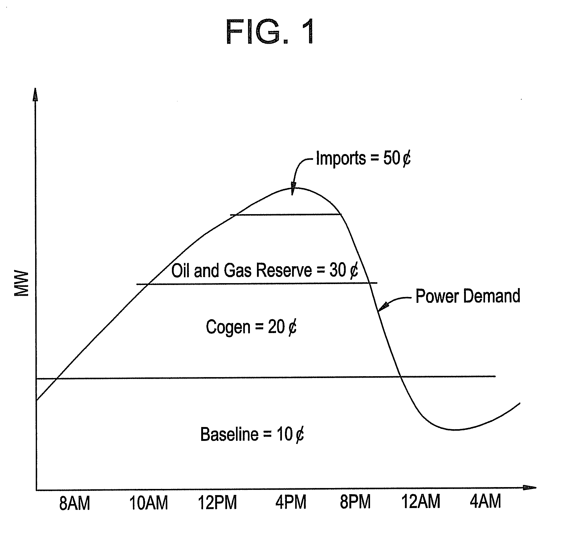
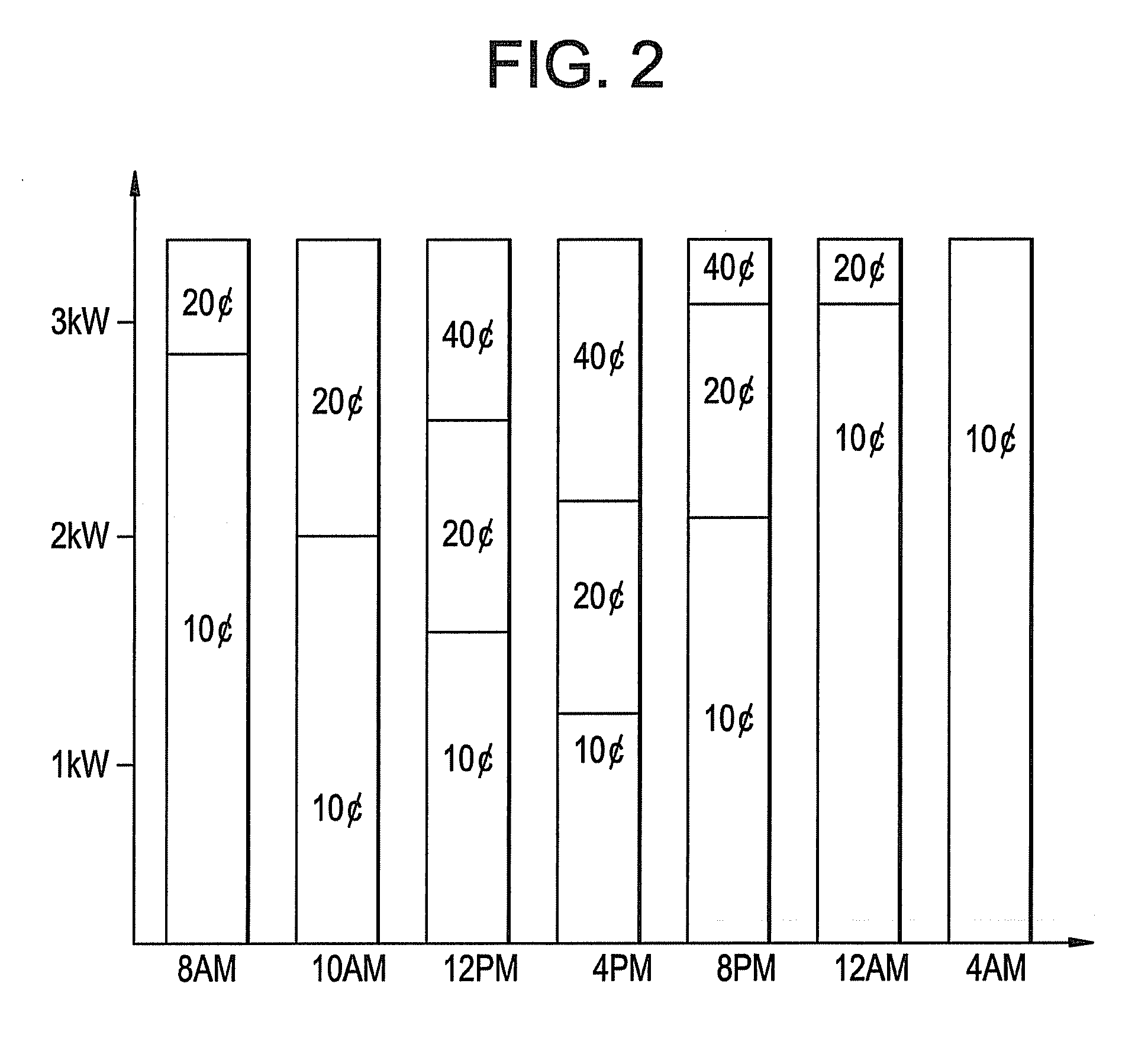
Currently, utilities generally charge some types of facilities, such as residential buildings, a flat rate per unit of energy delivered, but with increasing cost of fuel prices and high energy usage at certain parts of the day, utilities have to buy more energy to supply customers during peak demand, as illustrated in FIG. 1.
As demand increases, so does cost of power generation or supply.
But the cost may increase at additional levels of generation due to the need to tap into reserve generation capability and / or to purchase power from outside sources connected to the grid.
Thus, during peak demand, cost of energy production is highest, while at the lowest off-peak demand level, the cost of energy production is simply the baseline cost.
However, the solution provides no active control beyond the mere switching off the devices on and off.
However, such current peak shaving methods do not provide a maximal benefit for some energy consuming devices, such as a refrigerator will provide a maximal benefit.
However, not all utility companies, which number more than 3,000 in the U.S. for electricity providers, will use the same communication method in the AMI system.
Additionally, known systems do not communicate directly with the energy using devices.

Method used


Image

  • Energy management
  • Energy management
  • Energy management

Examples


Embodiment Construction

[0021]With reference to the accompanying Figures, examples of a facility energy management system and method according to embodiments of the invention are disclosed. For purposes of explanation, numerous specific details are shown in the drawings and set forth in the detailed description that follows in order to provide a thorough understanding of embodiments of the invention. It will be apparent, however, that embodiments of the invention may be practiced without these specific details. In other instances, well-known structures and devices are schematically shown in order to simplify the drawing.

[0022]The terminology used herein is for the purpose of describing particular embodiments only and is not intended to be limiting of the invention. As used herein, the singular forms “a”, “an” and “the” are intended to include the plural forms as well, unless the context clearly indicates otherwise. It will be further understood that the terms “comprises” and / or “comprising,” when used in t...


PUM


Abstract

An energy management system includes a module for an energy consuming device. The module has a module main controller including a computer processor in communication with a module computer readable storage medium containing computer executable code. When the computer executable code is executed by the computer processor, it performs a method including determining whether a demand state is a peak demand state, employing a reduced operational mode of the energy consuming device during a peak demand state, and employing a normal operational mode of the energy consuming device during a demand state other than a peak demand state. In an embodiment, the system also includes a system main controller in communication with the module.

Description

BACKGROUND OF THE INVENTION[0001]This disclosure relates to energy management, and more particularly to energy management of energy-using devices, such as, but not limited to, household consumer electronics devices and appliances. The disclosure finds particular application to varying energy consumption of a device or of a group of devices in accordance with demand on energy supply as a whole, demand of individual devices, priority of devices within a group of devices, and user preferences, can include changing existing appliances via add-on features or modules, and can include incorporating new energy saving features and functions into new appliances.[0002]Currently, utilities generally charge some types of facilities, such as residential buildings, a flat rate per unit of energy delivered, but with increasing cost of fuel prices and high energy usage at certain parts of the day, utilities have to buy more energy to supply customers during peak demand, as illustrated in FIG. 1. As ...

Claims


Application Information

Patent Timeline
IPC IPC(8): H04Q5/22G06F1/32
CPCH02J3/14H02J2003/143H02J2003/146Y04S20/242Y02B70/3266Y04S20/222Y04S20/224Y02B70/3225H02J2310/64H02J2310/14Y02B70/30Y04S50/10H02J2310/66
Inventor ROSCOE, GEORGE WILLIAMBESORE, JOHN KEITHILICKOVIC, DARKOPAPALLO, JR., THOMAS FREDERICKRIVERS, JR., CECILSCHORK, BRIAN MICHAEL
Owner GENERAL ELECTRIC CO
Learn More