Imaging apparatus

Inactive Publication Date: 2010-08-19
RICOH KK
View PDF18 Cites 10 Cited by
  • Summary
  • Abstract
  • Description
  • Claims
  • Application Information

AI Technical Summary

Benefits of technology

[0046]According to another aspect of the present invention, in an imaging apparatus of the present invention, an increased portion in power consumption consumed when an operation speed of the image pickup device is fastened in correspondence to the switch-over of display devices of an

Problems solved by technology

Optical finders other than the TTL format are difficult to realize a structure that fits into a small sized body and corresponds to a long focal point.
Incidentally, in the case an EVF is compared with a conventional LCD, the problems described hereinbelow are present.
That is, because the EVF 2 has a small display screen size, a user has to stare at a small screen area and this is problematic as the movement of a photogenic subject on the screen causes misalignment against the actual movement of the photogenic subject (speed of follow-up).
In addition, in the case where outdoor photographing is performed using a digital still camera, smearing, which is not problematic when monitoring is performed using a conventional LCD, is likely to become a problem in the case of the EVF 2.
In addition, when a user performs monitoring using the EVF 2, the user feels a sense of discomfort from the smearing generated due to the bright spot of a spotlight and an indoor fluorescent lamp, which is not generated in an optical finder
In this way, a digital still camera including the EVF 2 differs from a conventional LCD in that the EVF 2 is used as a substitute for an optical finder, and has unique problems.

Method used


Image

  • Imaging apparatus
  • Imaging apparatus
  • Imaging apparatus

Examples


Embodiment Construction

[0055]Preferred embodiments of a digital still camera as an imaging apparatus according to the present invention are described in detail with reference to the drawings hereinbelow. However, the constituent parts, type, combination, shape and the relative positions described in the following embodiments are not thought to be limited to only the scope of the descriptions unless there is a specific notation, but are only descriptive examples.

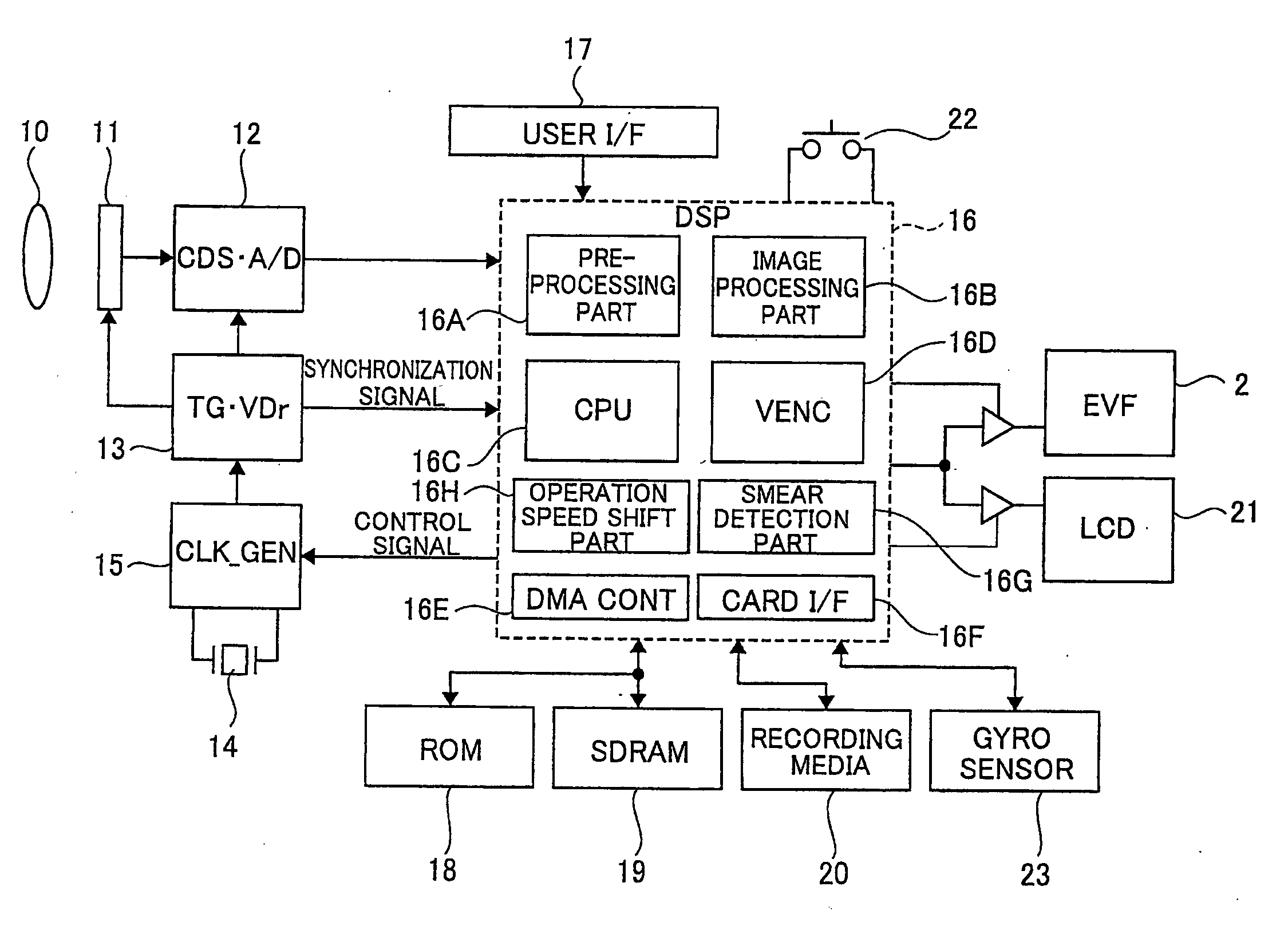
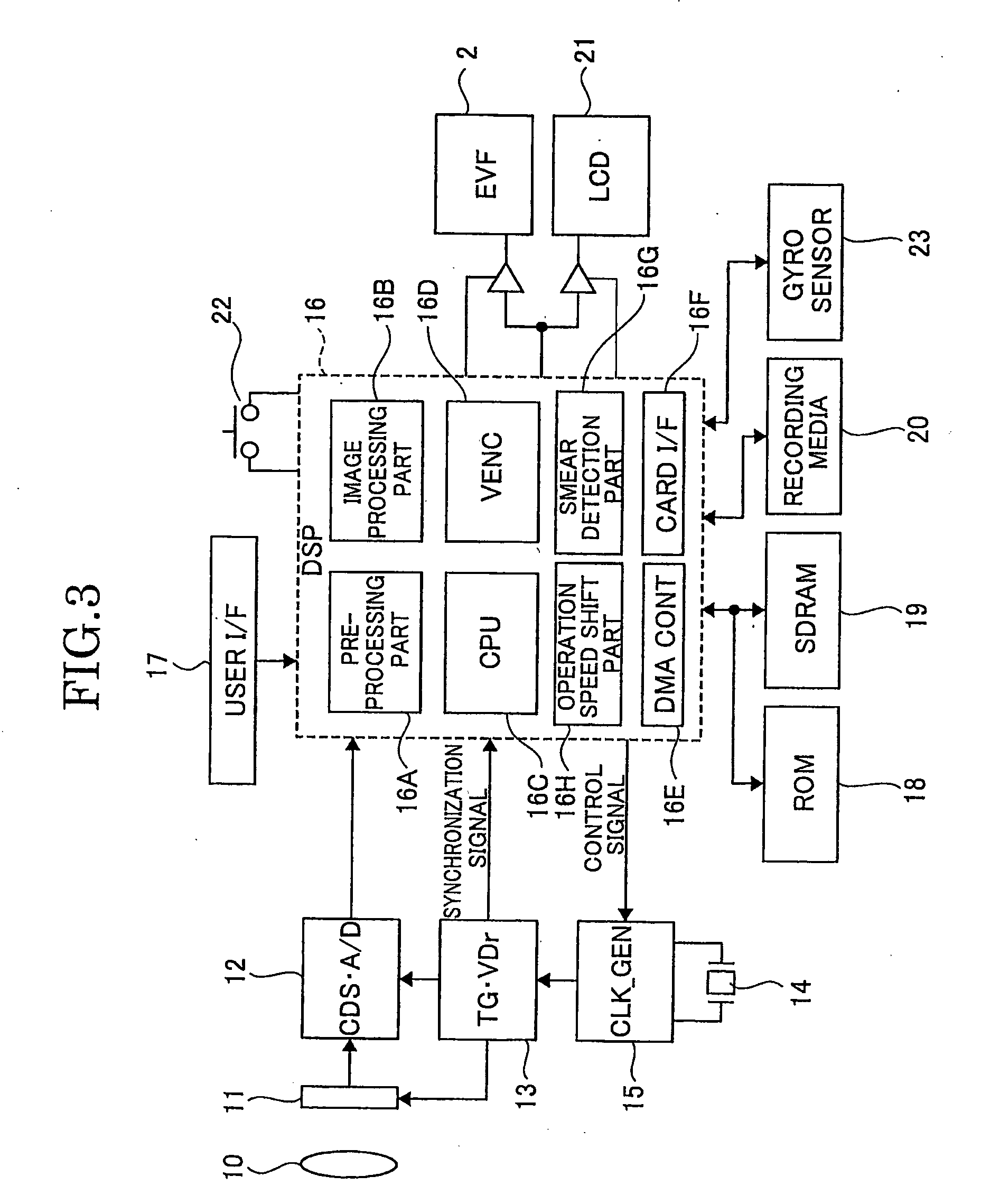
[0056]FIG. 3 is a block circuit diagram that illustrates schematically an imaging apparatus according to the present invention, which is, for example, applied to a digital still camera. In FIG. 3, the digital still camera includes an image pickup device 11, a drive part, a digital signal processing part 16, one image display part, another image display part, an image switch-over part 22, a clock signal supply part 15, an operation speed shift part, a smear detection part and a photogenic subject movement detection part. Specifically, 10 is an imagi...


PUM

PropertyMeasurementUnit
Poweraaaaaaaaaa
Speedaaaaaaaaaa
Areaaaaaaaaaaa

Abstract

An imaging apparatus includes an image pickup device that images a photogenic subject, a drive part that drives the image pickup device in order to read out image signals from the image pickup device, a digital signal processing part in which image signals outputted from the image pickup device are inputted and processed, one image display part connected to the digital signal processing part and configured to display using one display format a processed image, another image display part connected to the digital signal processing part and configured to display using another display format the processed image and which requires more time for display processing than the time required for display processing by the one display format and an image switch-over part for switching over an image display device between the one image display part and the another image display part. The digital signal processing part includes an operation speed shift part for setting the speed of operation of the drive part in correspondence to the switch-over of an image display device from the one image display part to the another image display part and a smear detection part for detecting smears based on image data obtained from the image pickup device. When smears are not detected based on the detection result of the smear detection part, the digital signal processing part maintains the speed of operation when an image is displayed in the another image display part to the speed of operation when an image is displayed in the one image display part.

Description

CROSS-REFERENCE TO RELATED APPLICATION[0001]This application is based on and claims priority from Japanese Patent Application No. 2007-193192, filed on Jul. 25, 2007, the disclosure of which is incorporated herein by reference in its entirety.TECHNICAL FIELD[0002]The present invention relates to an improvement in an imaging apparatus such as a digital camera.BACKGROUND ART[0003]In most imaging apparatuses, for example, digital still cameras, an optical finder is included. In recent years, in technological fields of digital still cameras, the development of optical finders has progressed towards the direction of small sized, longer focal point devices. Optical finders of the digital still cameras include optical finders of a TTL format in which a photogenic subject image based on light passing through an imaging lens system is viewed and optical finders of a format other than the TTL format.[0004]Optical finders other than the TTL format are difficult to realize a structure that fits...

Claims


Application Information

Patent Timeline
IPC IPC(8): H04N9/64H04N5/228G03B13/06H04N5/225H04N5/232H04N101/00
CPCH04N5/23293Y10T82/17H04N2101/00H04N5/3595H04N23/651H04N23/63H04N25/625H04N25/00
Inventor NAKAHIRA, TOSHIAKI
Owner RICOH KK
Why Eureka
Try Eureka