Supercharge Your Innovation With Domain-Expert AI Agents!

Vibration isolation section

a technology of vibration isolation and section, which is applied in the field of vibration isolation sections, can solve the problems of mechanical noise generation, noise that affects streamers, and types of noise created, and achieve the effects of low offset, low noise, and low stiffness

Active Publication Date: 2010-08-19
PHOENIX ENG SYST
View PDF6 Cites 5 Cited by
  • Summary
  • Abstract
  • Description
  • Claims
  • Application Information

AI Technical Summary

Benefits of technology

[0019]The present invention advantageously provides a vibration isolation section which provides the performance and operational advantages of the radial stretch concept without necessitating the use of an inner sealed volume of liquid.
[0020]In preferred embodiments the helical wrap angle achievable is advantageously not limited in the same way as for the constant volume liquid model. Fibres may be arranged at angles higher than 55 degrees and will go into tension for any axial strain. This means that it is possible to design structures with a lower stiffness than is possible with the constant volume liquid model for the same diameter and length.
[0021]The low stiffness achievable with the present invention enables short lengths to be achieved leading to low offsets that are desirable in seismic operations. This low stiffness also allows high levels of attenuation to be achieved at low frequencies.

Problems solved by technology

A particular issue that concerns marine seismic survey acquisition systems is a type of noise created by movement of the water past the lead in cable and the spreader cable.
The noise is sometimes known as strumming and such noise can be of a nature so as to materially adversely affect the quality of the seismic signals detected by the sensors in the streamers.
Other types of noise that affect the streamers include mechanically generated noise in the diverters and fluctuations in the towing speed caused by variations in water conditions.
However, they have several significant disadvantages which are that their length leads to longer offsets for the streamer relative to the source, they are easily damaged and are filled with an oil-based fluid which presents environmental and safety issues.
These products tend to have good attenuation at frequencies lower than around 8 Hz due to the low overall stiffness afforded by the long length.
Such products tend to be very heavy and, due to their large diameter, cannot be handled by the normal streamer handling and storage equipment fitted in seismic vessels and need to be manually added into the streamer on deployment and removed out of the streamer on recovery.
This presents significant operational efficiency problems as well as health and safety problems to the seismic operators.
The product generally has poorer attenuation at frequencies higher than about 12 Hz due to a relatively low loss tangent and very short length.
In the constant volume model, the highest angle achievable is in the region of 55 degrees and this represents a limit to the design.
However, it has been noted that this product is not effective at frequencies less than around 3 Hz.
The key disadvantage of this product is that medium axial loads are translated into very high pressures in the fixed volume of oil, typically a 20 KN axial load could translate into a 50 bar internal pressure.
Because the product relies on a fixed volume, any kind of small puncture of the hose, or failure of various seals and joints in the product leads to loss of liquid and inevitable failure of the stretch.
Furthermore, the leakage itself, which may be high pressure, presents health, safety and environmental problems for the seismic contractor.
The hose construction and the presence of very high pressures in the liquid during normal operations can render the product more likely to suffer a failure in the field.
The attenuation performance of the device in the 3 Hz to 10 Hz range can be very good due to the low stiffness achievable but performance at higher frequencies is typically poor due to the typically low loss tangent of the shock cords.
However, it has been noted that the device does not offer useful attenuation in the sub-3 Hz range.
The key disadvantage is that such products cannot be handled easily by the normal streamer handling and storage equipment fitted in seismic vessels and need to be manually added into the streamer on deployment and removed out of the streamer on recovery.
This presents significant operational efficiency problems as well as health and safety problems to the seismic operators.

Method used


Image

  • Vibration isolation section
  • Vibration isolation section
  • Vibration isolation section

Examples


Embodiment Construction

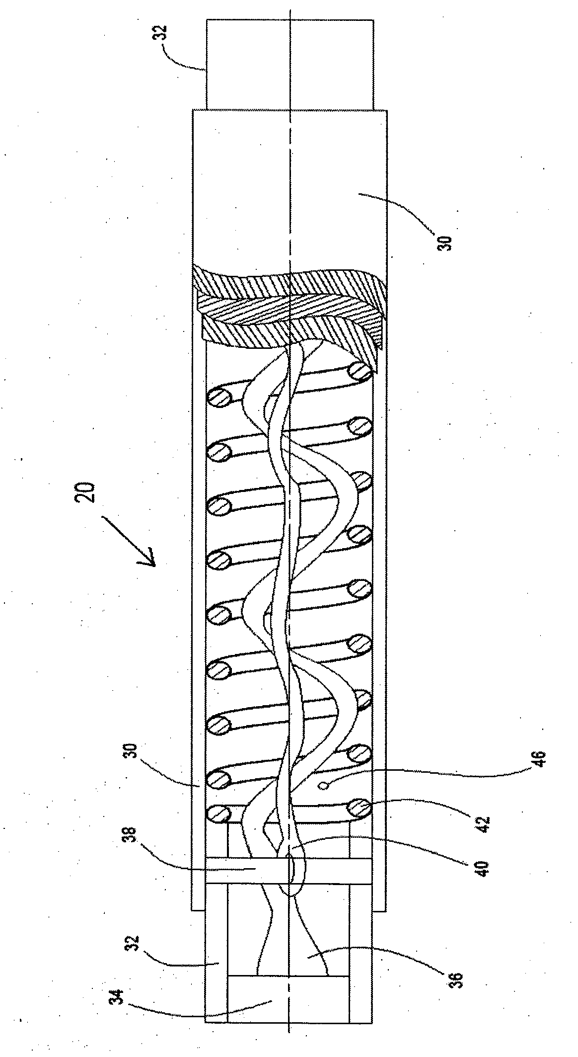
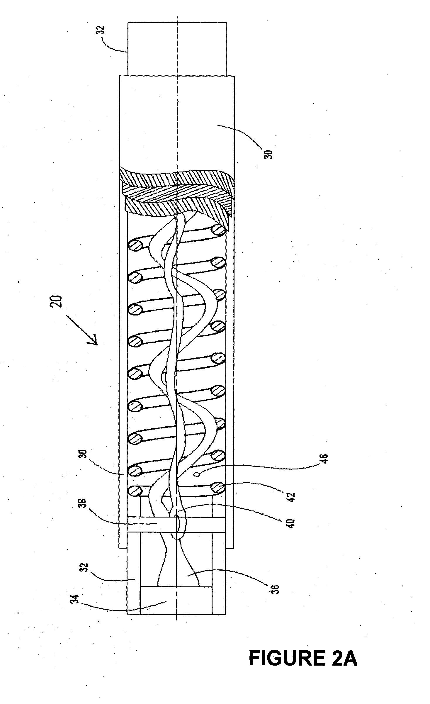
[0026]It is to be noted where possible features common to the various embodiments illustrated in the drawings are referred to in each drawing by a respective common feature number.

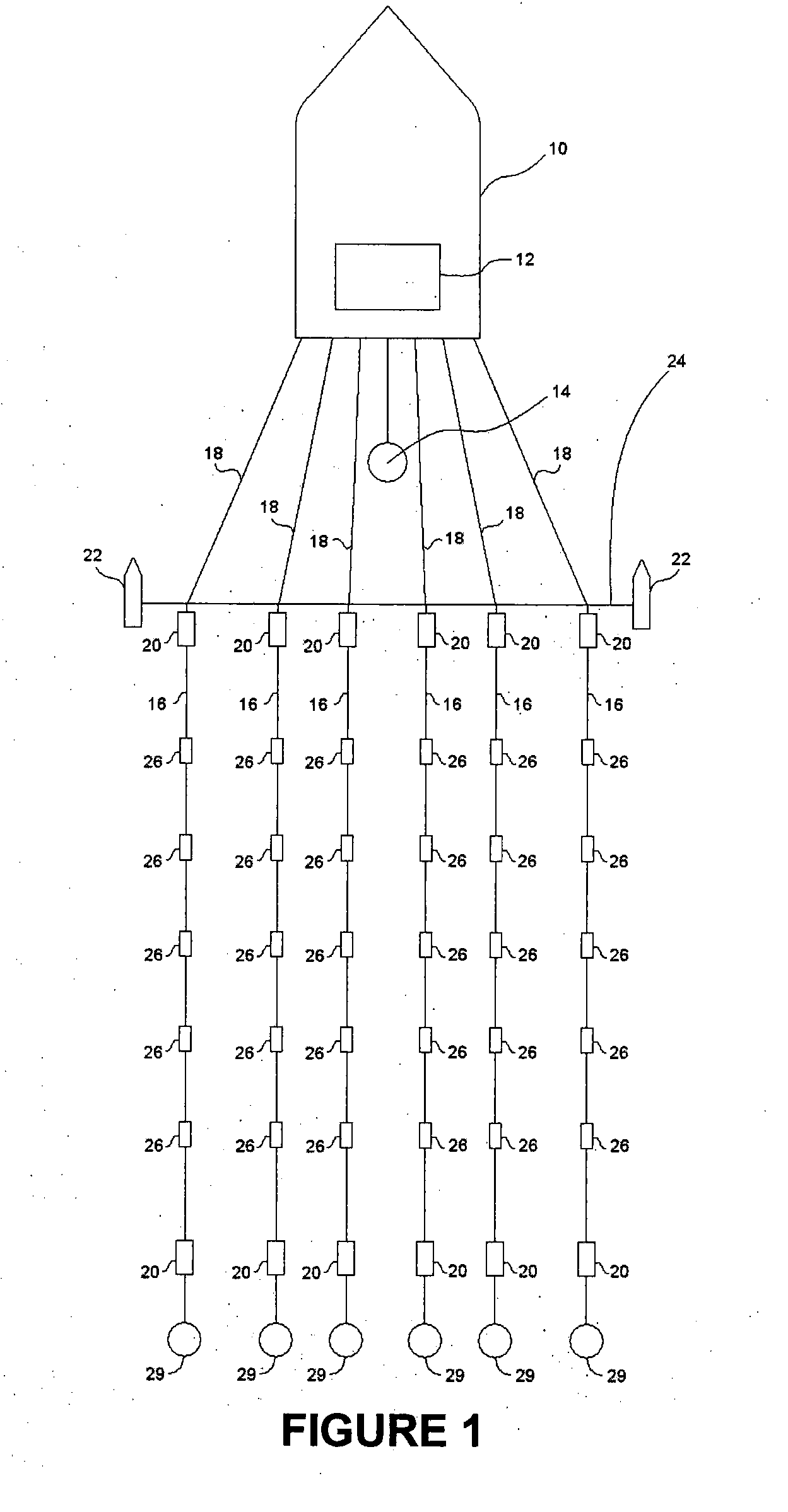
[0027]A marine seismic acquisition system is shown in FIG. 1. The seismic data acquisition system includes a seismic vessel 10 towing a plurality of laterally spaced apart seismic streamers 16 through a body of water such as a lake or the ocean. The seismic vessel 10 typically includes instrumentation thereon collectively called a recording system, shown generally at 12. The recording system 12 may include navigation devices, electrical power supplies, data recording equipment and seismic source actuation equipment of types well known in the art. The data recording equipment (not shown separately for clarity of the illustration) makes recordings, typically indexed with respect to time of actuation of a seismic energy source 14, of signals detected by seismic sensors 26 disposed at spaced apart locations al...


PUM


Abstract

According to the present invention there is provided a vibration isolation section for use in a seismic streamer system, the section including:a resilient sheath arranged to be connected end-to-end in a seismic streamer system and receive axial loads transmitted through the system, wherein the resilient sheath is configured to stretch upon receiving an axial load and substantially convert the axial load into a radial stress; anda support structure housed within the resilient sheath, the support structure including one or more members having substantially constant diameter under load which provides a reaction to the radial stress, thereby providing attenuation to the received axial load.

Description

FIELD OF THE INVENTION[0001]The present invention relates generally to the field of marine seismic survey apparatus. More particularly, the invention relates to vibration isolation sections, otherwise known as stretch sections, used in marine seismic streamer systems to reduce noise.PRIOR ART[0002]It is to be noted that a reference to prior art herein is not an admission that the prior art is common general knowledge to a person skilled in the art or any other person in any sense whatsoever.[0003]Marine seismic survey apparatus typically include arrays of seismic sensors disposed in a structure that is towed by a seismic vessel through a body of water, such as a lake or the ocean. Such seismic receiver structures are commonly known as streamers.[0004]Streamers are typically made in segments of about 75, 100 or 150 m in length. A streamer may include 100 or more such segments coupled end-to-end to form the complete streamer. Each streamer segment generally includes one or more high s...

Claims


Application Information

Patent Timeline
IPC IPC(8): G01V1/38
CPCG01V2001/205G01V1/201
Inventor GALLAGHER, ANDREW JOHNWALLACE, DONALD INNES
Owner PHOENIX ENG SYST
Features
  • R&D
  • Intellectual Property
  • Life Sciences
  • Materials
  • Tech Scout
  • Unparalleled Data Quality
  • Higher Quality Content
  • 60% Fewer Hallucinations
Learn More