

Heating and cooling control methods and systems
a control method and technology of heat and cooling, applied in the field of heat, ventilation and air conditioning (hvac), can solve the problems of system sampling outside air, non-compliance, and inability to meet, and achieve the effect of improving energy efficiency
- Summary
- Abstract
- Description
- Claims
- Application Information
AI Technical Summary
Benefits of technology
Problems solved by technology
Method used
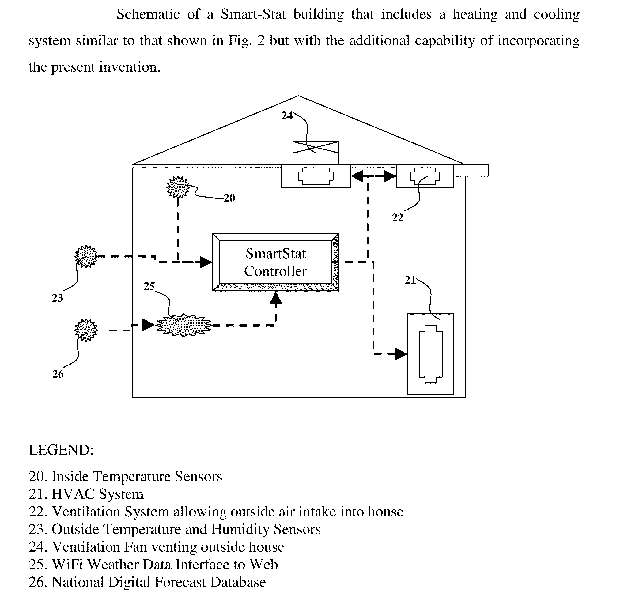
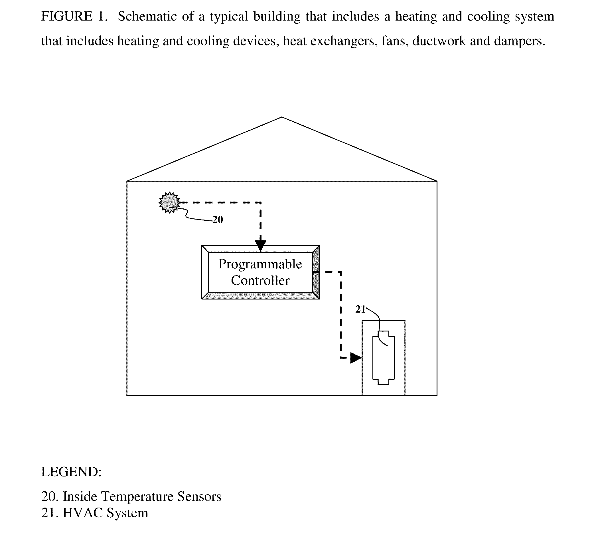
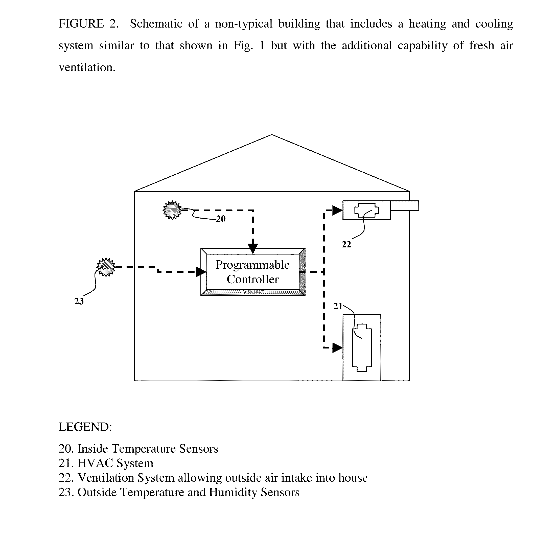
Image

Examples
example 1
[0051]A whole-house fan (e.g., a typical direct-drive or belt-drive and thermally-protected fan is obtained DIY suppliers) was modified to fit an insulated opening in the ceiling of a conventional insulated two-story timber-framed house. The fan is controlled manually by a hand-held switch and used in conjunction with open or closed windows. The fan is conventional, multi-speed, 3-bladed and capable of blowing air at more than 1,000 cubic feet per minute. By controlling the fan in different environmental conditions throughout the year, we determined that outside air is an effective way of cooling a house when outside temperature and humidity is suitable. The system was not very effective when windows were partially closed and almost completely ineffective when windows were completely closed.
example 2
[0052]Daily maximum and minimum temperature data as well as hourly temperature data for different cities and states were downloaded from publicly available databases (e.g., Iowa Environmental Mesonet). These data were from different years such as 2000, 2001, 2002, 2003, 2004, 2005, 2006, 2007. A computer modeling spreadsheet was devised to evaluate and compare the costs of using a conventional thermostat controller compared with the present invention. The modeling system was also evaluative, allowing different methods of control and different set-points to be evaluated. Using this system we found that energy savings of up to 25% were possible on certain times of day and on different days energy savings of an extra 15% were possible. Savings were not possible on all days of the year but in no case was the present invention less efficient when compared with our model of a conventional thermostatic controller.
[0053]We concluded that the present invention has the potential to decrease e...
example 3
[0054]Thermal heat loss equations (see table below) can be calculated based on Heat Loss equations (Simplified design of HVAC systems. William Bobenhausen, 1994, Technology & Engineering) or U-factors (quantified as BTU / ft2·° F.·hr). Using information provided in chapter 5 we computed the U-factor for different rooms by using the published BTU / ° F.·hr. There was considerable variation between rooms even in the same house (ranging from 0.1 to 0.3 BTU / sq.ft.·° F.·hr). It is obvious that the range of variation in thermal loss values will be even greater between different houses.
Heat Loss(BTU / Surface AreaThermal Loss (UA)° F. hr)(sq. ft)(BTU / sq. ft. ° F. hr)Room A (15 × 10 × 10)46.31500.309Room B (15 × 20 × 10)553000.183Room C (10 × 10 × 10)9.71000.097Room D (15 × 15 × 10)63.32250.281Room E (10 × 15 × 10)401500.267Room F (6 × 15 × 10)14900.156Room G (12 × 15 × 10)23.41800.130Room H (9 × 15 × 10)26.61350.197Total / Average34.913300.203Building Thermal heat loss equation: (QA = U · A · (Ti ...
PUM
 Abstract
Description
Claims
Application Information