
Weight plate of vacuum evaporation apparatus and vacuum evaporation apparatus using the same

a vacuum evaporation apparatus and weight plate technology, applied in vacuum evaporation coatings, chemical vapor deposition coatings, coatings, etc., can solve problems such as color shift, color irregularities, impact or vibration, and image disturban

Inactive Publication Date: 2010-08-26
CANON KK +1
View PDF0 Cites 11 Cited by
  • Summary
  • Abstract
  • Description
  • Claims
  • Application Information

AI Technical Summary

Benefits of technology

[0014]It is an object of the present invention to provide a weight plate of a vacuum evaporation apparatus that may hold a positional relationship between a shadow mask and a glass substrate after superposing and aligning the shadow mask and the glass substrate, and may prevent occurrence of a displacement between the shadow mask and the glass substrate due to a vibration or an impact during conveyance by a convey mechanism.
[0016]The present invention having the above-mentioned structure may provide the following effect.
[0017]The weight plate is placed on the glass substrate that is superposed and aligned on the shadow mask that is fixed to the mask holding member. This weight plate has a shock absorbing unit for reducing an impact due to conveyance in the in-plane direction of the substrate, and forms a combined conveyance body by pressing the glass substrate to the shadow mask to hold the glass substrate by gravity. As a result, it is possible to reduce a vibration or an impact due to a collision or the like, and hence occurrence of a displacement between the shadow mask and the glass substrate may be prevented.

Problems solved by technology

Therefore, their impact force may cause displacement between the shadow mask and the glass substrate, and the positional accuracy thereof may deviate from a target value, thereby resulting in various problems such as color shift, color irregularity, no emission, and the like.
When those convey mechanisms are used and intended to increase in convey speed of the substrate, an impact or a vibration occurs due to the acceleration or deceleration.
A difference of the impact forces applied to the substrate holder and the substrate may cause a displacement.
However, magnetic force may cause an image disturbance in the production process of the organic EL panel.
In particular, it is said that if a stripe mask is used, magnetic lines of flux are generated so that a distance between the stripe masks varies, resulting in an image disturbance due to a displacement of a film forming position of an organic light emission film.

Method used


Image

  • Weight plate of vacuum evaporation apparatus and vacuum evaporation apparatus using the same
  • Weight plate of vacuum evaporation apparatus and vacuum evaporation apparatus using the same
  • Weight plate of vacuum evaporation apparatus and vacuum evaporation apparatus using the same

Examples


first embodiment

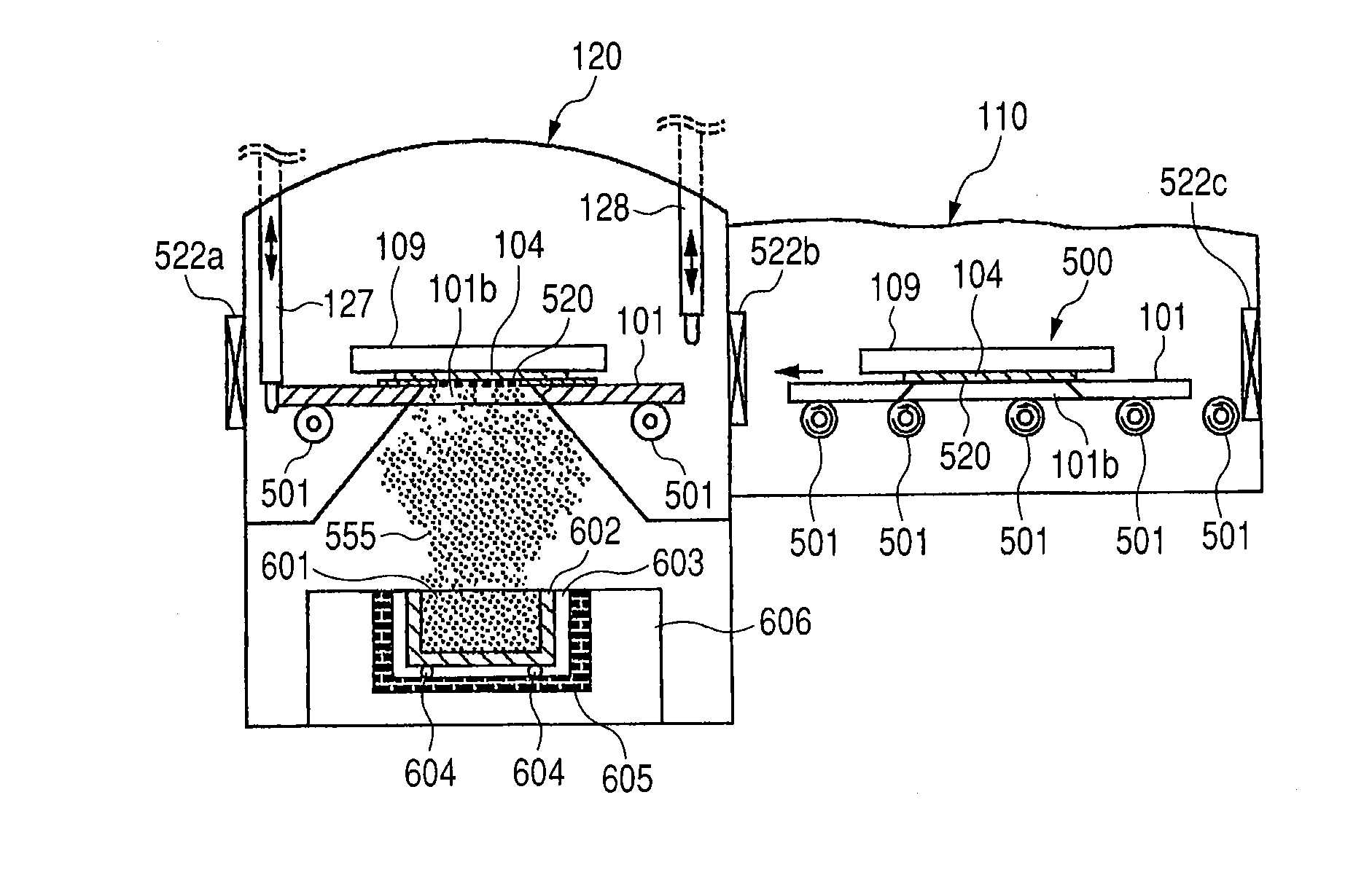
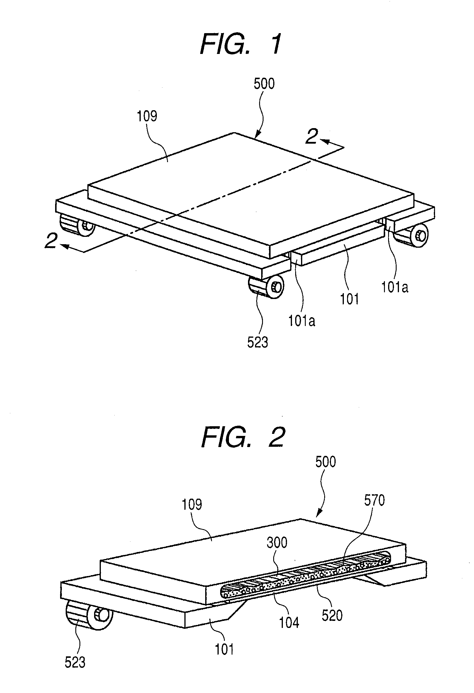
[0035]FIGS. 1 and 2 illustrate a weight plate according to a In a vacuum evaporation apparatus for performing vacuum evaporation, a combined conveyance body 500 is placed on a conveyor roller 523 as a convey mechanism. Under a weight plate 109, a glass substrate 104 on which TFTs are formed is placed in a state sandwiched between a tension mask 520 and the weight plate 109. The tension mask 520 is provided with fine pores 520a for transmitting organic EL evaporation particles 555 (see FIG. 11), which are aligned and arranged with an accuracy of ±2 μm or smaller with respect to the pixels of the TFTs.

[0036]After finishing the alignment, the combined conveyance body 500 is conveyed to the conveyance chamber. At this time, acceleration is applied to the combined conveyance body 500 by rotation of the roller 523. In this case, if the weight plate 109 is a simple rigid metal without the shock absorbing unit, the impact force of acceleration applied to the weight plate is transferred to ...

second embodiment

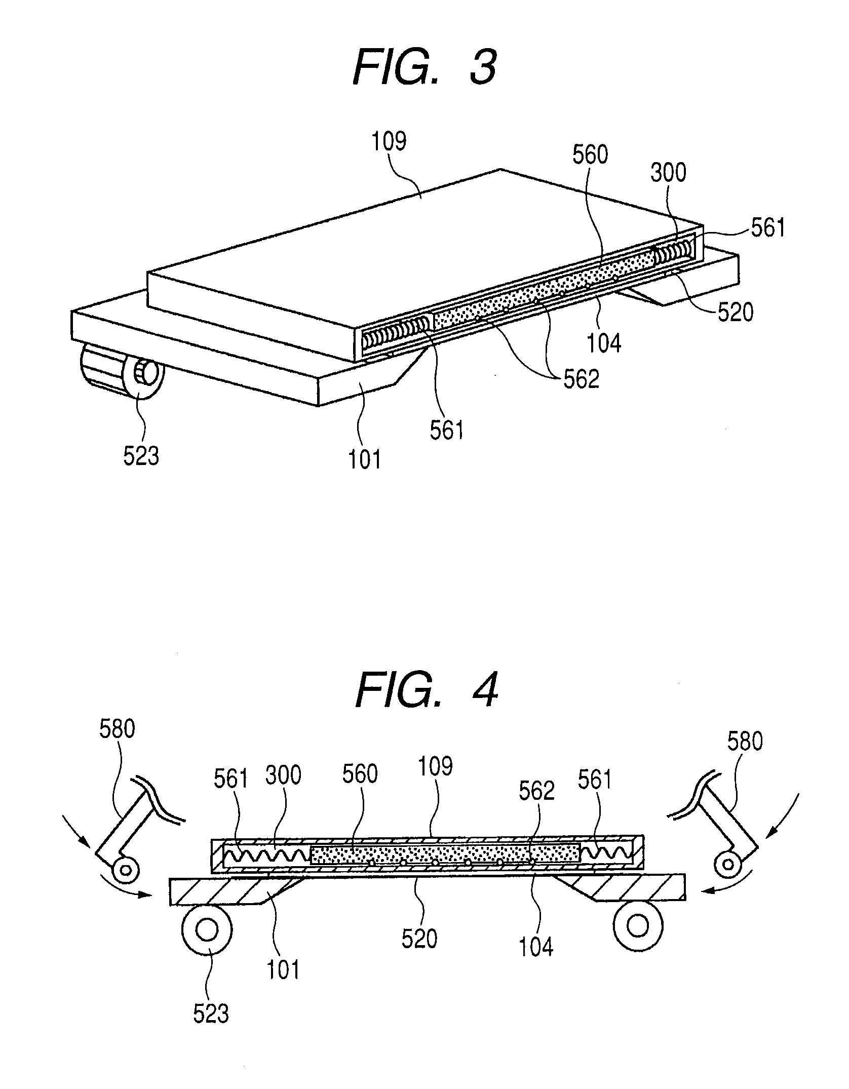
[0043]FIG. 3 illustrates a weight plate according to a The weight plate 109 has the hollow part 300, and, in the hollow part 300, a sliding body 560 is disposed so that the sliding body 560 is connected via springs 561 for reducing impact between inner wall surfaces of the hollow part. The springs 561 are illustrated at only the right and the left in FIG. 3, but they may be disposed also in the front and rear direction (in the direction of the front face and the back face in FIG. 3). Alternatively, if there may be conveyance and collision in the vertical direction, the springs may be disposed in the vertical direction.

[0044]In addition, if the sliding body 560 is enclosed and shielded completely in the weight plate 109, the springs 561 which are used inside the weight plate 109 may be made of an organic material (e.g., polyurethane resin, polyethylene, and the like) that is apt to generate gas or a flexible member made of rubber material or the like. In addition, a shape thereof ma...

fourth embodiment

[0072]FIG. 13 is a schematic enlarged cross sectional view illustrating a weight plate according to a The sliding body 560 is provided with multiple recesses 564 each including a spring 563 and a slide ball 562 set therein. The slide balls 562 securely press the sagged glass substrate 104 so as to maintain contact between the mask part in which only the tension mask 520 is disposed (tension mask area other than a so-called mask frame) and the glass substrate 104. Note that the description uses the sliding body 560 of this embodiment, but it is possible not to provide the sliding body 560 in particular but to provide the springs 563 and the slide balls 562 directly to the weight plate. In this case, it is possible to provide multiple recesses 564 to the weight plate and to dispose the spring 563 and the slide ball 562 in the recess 564.

[0073]The recess 564 has a cylindrical shape in FIG. 13, but actually a hole having a diameter smaller than that of the slide ball 562 is formed so t...


PUM

PropertyMeasurementUnit
accelerationaaaaaaaaaa
thicknessaaaaaaaaaa
thicknessaaaaaaaaaa

Abstract

Provided is a weight plate of a vacuum evaporation apparatus, and a vacuum evaporation apparatus, which may prevent occurrence of displacement due to an impact or the like during a conveyance by a convey mechanism after a shadow mask and a glass substrate are superposed and aligned. The glass substrate is superposed and aligned on a top surface of a tension mask as the shadow mask fixed to a mask holding member. Then, the weight plate is placed on the glass substrate and presses the glass substrate by gravity to form a combined conveyance body. A liquid metal is filled in a hollow part of the weight plate at a filling factor of from more than 25% to less than 85% or other shock absorbing mechanism is provided for absorbing an impact applied to the combined conveyance body.

Description

BACKGROUND OF THE INVENTION[0001]1. Field of the Invention[0002]The present invention relates to a weight plate of a vacuum evaporation apparatus for pressing by gravity so as to prevent displacement between a shadow mask and a glass substrate that are superposed and aligned in a vacuum evaporation apparatus, and to the vacuum evaporation apparatus using the same.[0003]2. Description of the Related Art[0004]In a production process of an organic EL panel that supports full color light emission, red (R), green (G), and blue (B) color elements are formed on a glass substrate by a vacuum evaporation process using a shadow mask.[0005]A method which is widely adopted for forming the color element of each color includes the steps of making shadow masks for individual RGB colors, aligning the shadow mask for each color, and performing vacuum evaporation on the glass substrate.[0006]The shadow mask and the glass substrate are fixed with a holding member and conveyed through a plurality of fi...

Claims


Application Information

Patent Timeline
Patent Type & Authority Applications(United States)
IPC IPC(8): C23C14/24
CPCC23C14/042C23C14/568C23C14/50
Inventor EIDA, MASATAKASODA, TAKEHIKOMIYATA, KAZUSHI
Owner CANON KK
Learn More