Energy recovery apparatus

Inactive Publication Date: 2010-08-26
EBERLE GIORGIO +1
View PDF15 Cites 2 Cited by
  • Summary
  • Abstract
  • Description
  • Claims
  • Application Information

AI Technical Summary

Benefits of technology

[0006]The aim of the present invention is to solve the above-mentioned technical problems, eliminating the drawbacks of the cited background art, by providing a device which allows the reduction of emissions of particulates and pollutants and the reduction of the temperature of the exhaust gases released from flues and simultaneous recovery of part of the heat energy of the exhaust gases.
[0007]Within this aim, an object of the invention is to provide a device that allows reduction of the output temperature of the exhaust gases from the stacks or flues.
[0008]Another object of the invention is to make it possible to improve the energy balance of industrial / civil heating systems by lowering their operating costs.
[0009]Another object is to obtain a device that is effective, structurally simple, has low manufacturing costs and can be provided with conventional known systems.

Problems solved by technology

Moreover, the use of these boilers requires considerable energy resources and has high costs for operation in addition to the drawback consisting in the release of a quantity of hot exhaust gases at high temperature into the environment, which gases still have heat energy that is dispersed into the environment, altering the surrounding bioclimate.

Method used


Image

  • Energy recovery apparatus
  • Energy recovery apparatus
  • Energy recovery apparatus

Examples


Embodiment Construction

[0017]In the exemplary embodiments that follow, individual characteristics, given in relation to specific examples, may actually be interchanged with other different characteristics that exist in other exemplary embodiments.

[0018]Moreover, it is noted that anything found to be already known during the patenting process is understood not to be claimed and to be the subject of a disclaimer.

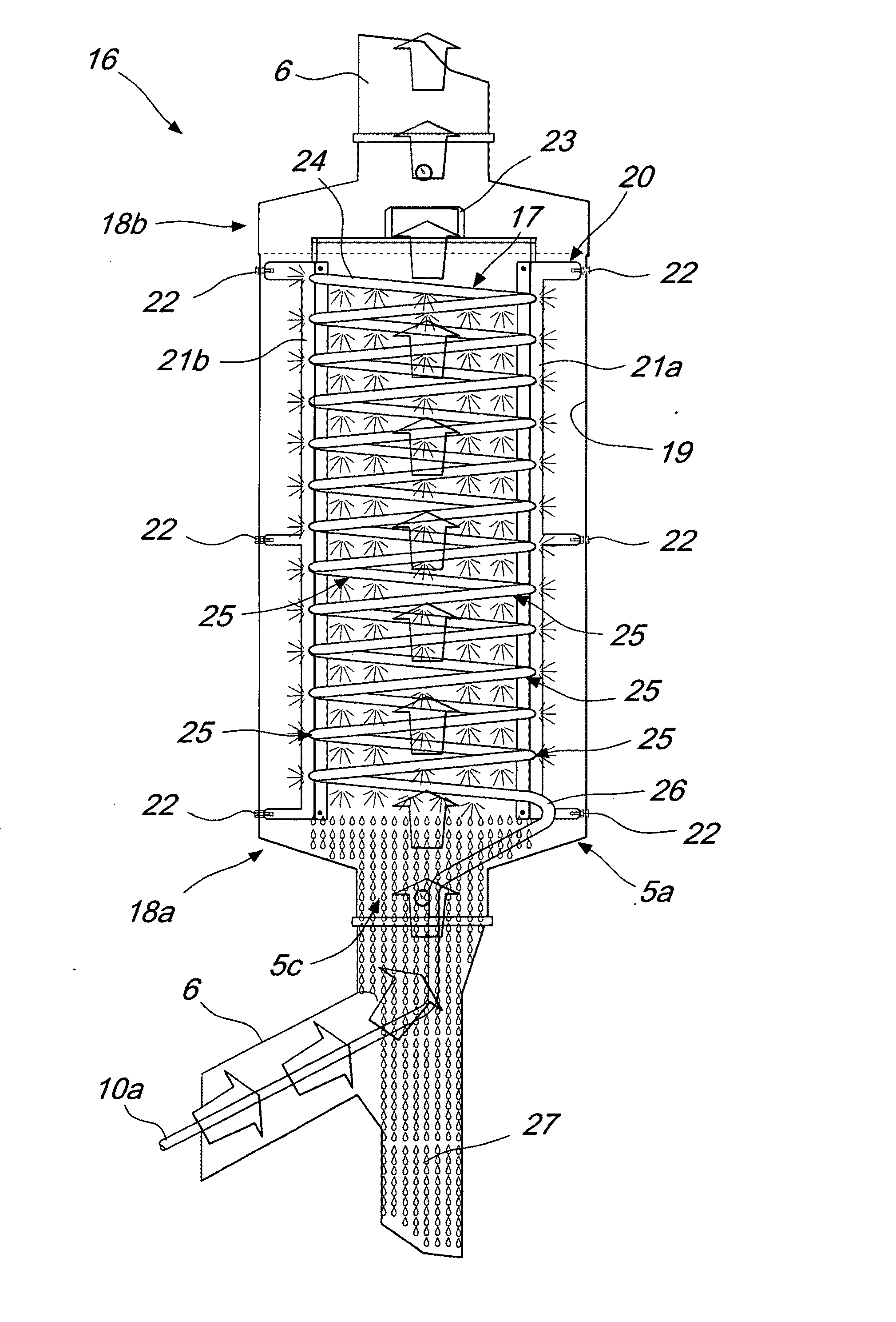
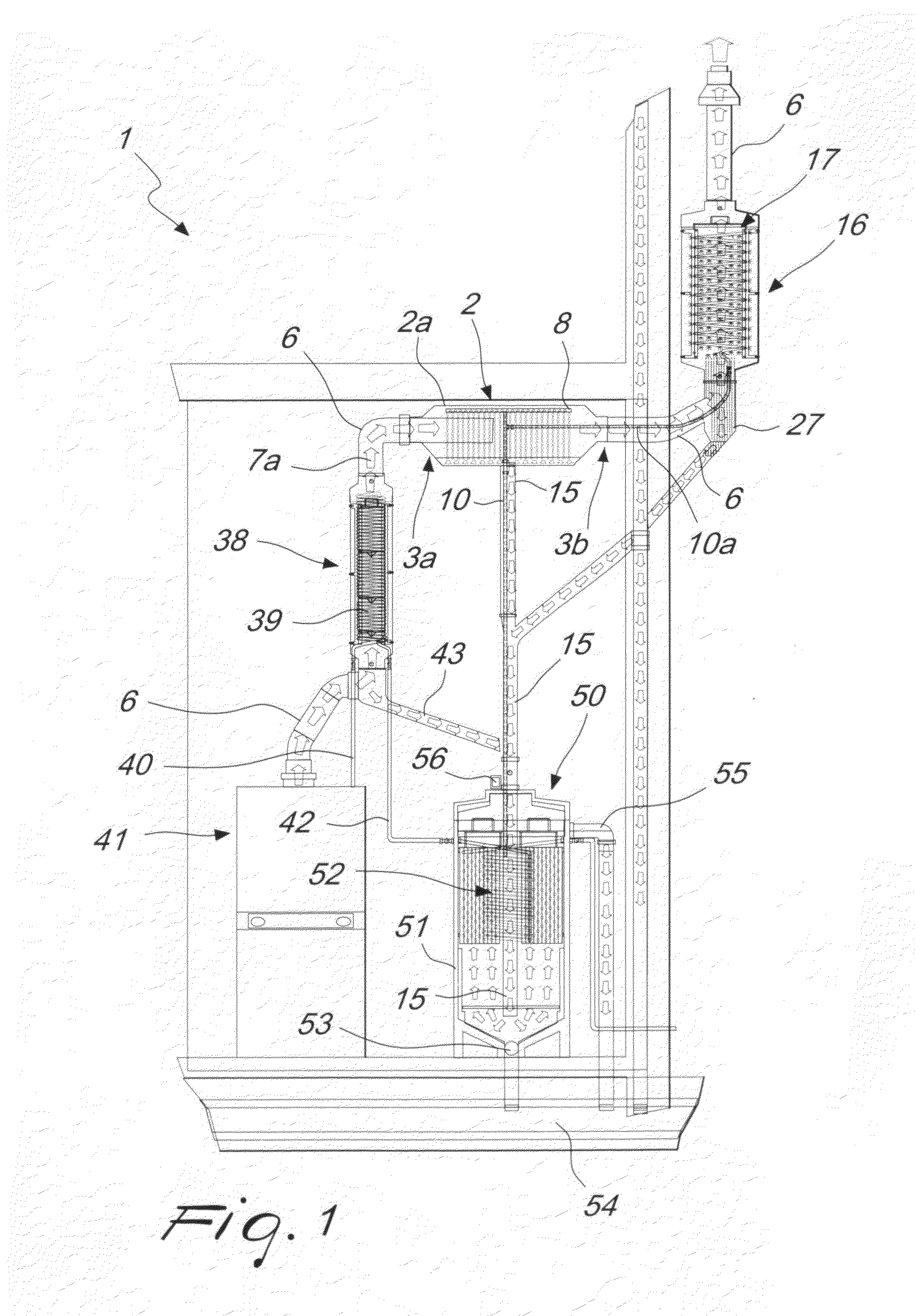
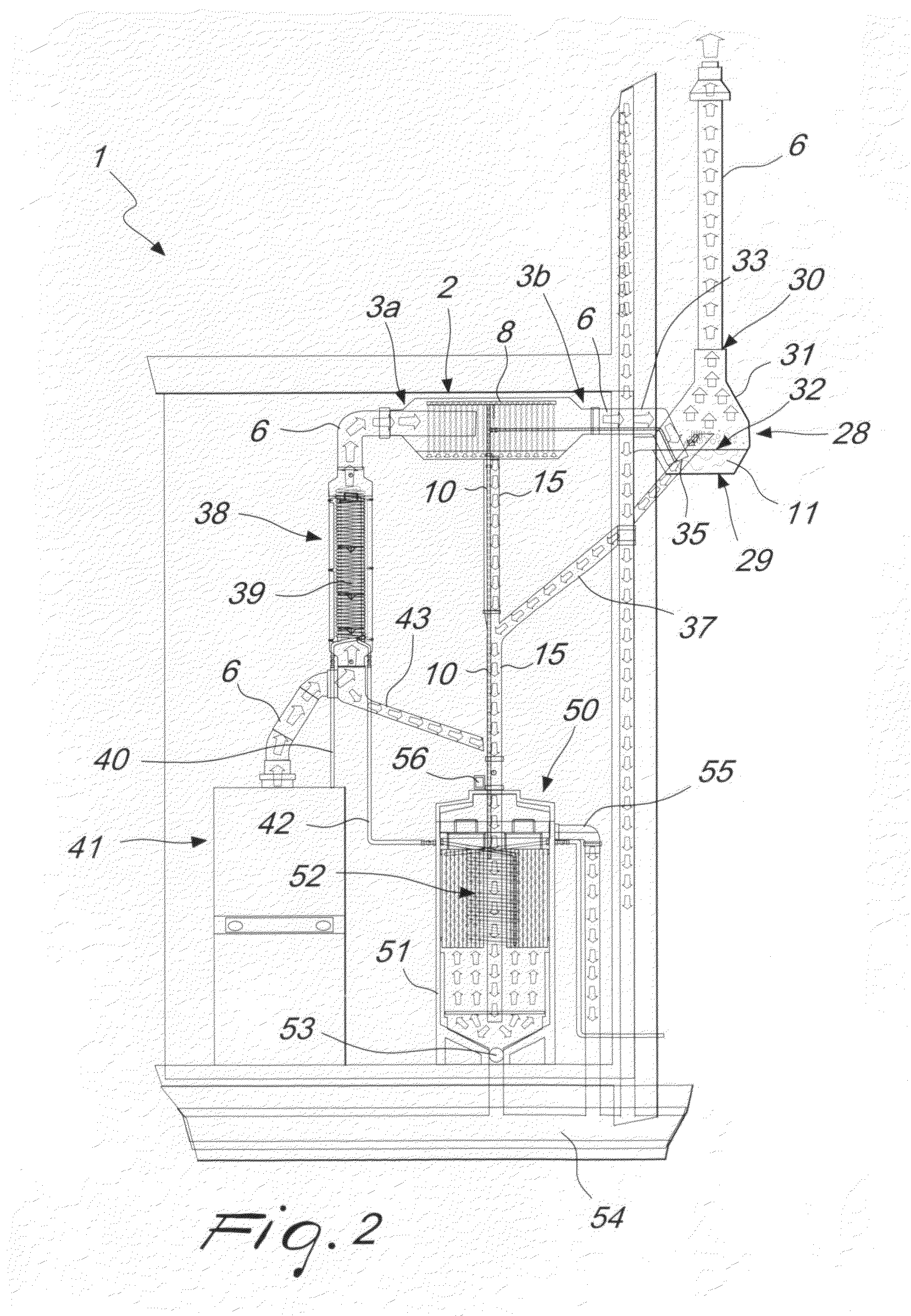
[0019]With reference to the figures, the reference numeral 1 designates an energy recovery apparatus, consisting of a first hollow tubular element 2, which is elongated and preferably has a substantially cylindrical cross-section with a preferably flat top 2a, which has, proximately to a first end 3a and a second end 3b, a preferably frustum-shaped tapering portion 4a, 4b for connection to a first opening and a second opening 5a, 5b that have a preferably circular cross-section, respectively for inflow and outflow.

[0020]The first and second openings 5a, 5b are connected at a portion of a flue or sta...


PUM


Abstract

An energy recovery apparatus for heating or industrial systems that entail the combustion of products, comprises a tubular element, which is arranged at a portion of a stack or flue and is provided with a delivery for feeding water for scrubbing exhaust gases. The tubular element has an outlet for collecting the treated water that can be conveyed to a heat exchanger. The apparatus allows reduction of the emission of particulates and pollutants into the environment and makes it possible to achieve a reduction in the temperature of the exhaust gases as well as heat energy recovery.

Description

[0001]The present invention relates to an energy recovery apparatus.BACKGROUND OF THE INVENTION[0002]Currently it is known that boilers are used to heat water for residential and industrial uses.[0003]These boilers are supplied by means of fuels which, by burning, release exhaust gases which are expelled by means of stacks or flues.[0004]The combustion that occurs inside boilers inherently produces particulates and pollutants whose amount can vary as a function of the fuel used.[0005]Moreover, the use of these boilers requires considerable energy resources and has high costs for operation in addition to the drawback consisting in the release of a quantity of hot exhaust gases at high temperature into the environment, which gases still have heat energy that is dispersed into the environment, altering the surrounding bioclimate.SUMMARY OF THE INVENTION[0006]The aim of the present invention is to solve the above-mentioned technical problems, eliminating the drawbacks of the cited backg...

Claims


Application Information

Patent Timeline
IPC IPC(8): F22D1/02F24D12/02F28D1/047
CPCF23J15/04F23J2219/40F23J2217/50
Inventor EBERLE, GIORGIOMAZZEGA, MASSIMO
Owner EBERLE GIORGIO
Why Eureka
Try Eureka