Exhaust system for an internal combustion engine and method for operating the same

Pending Publication Date: 2020-07-23
VOLKSWAGEN AG
View PDF0 Cites 3 Cited by
  • Summary
  • Abstract
  • Description
  • Claims
  • Application Information

AI Technical Summary

Benefits of technology

[0021]Alternatively, the internal combustion engine is operated with a slightly rich lambda value of λe<1, and the burner is operated with a slightly lean lambda value of λb<1, in such a way that the mixed gas is stoichiometric with λm=1. This has the advantage that the particulate emissions of the burner during the slightly lean operation are reduced, and the increased content of CO and HC in the exhaust gas results in further acceleration in the heating of the second exha

Problems solved by technology

These methods allow only limited heating power, and are associat

Method used


Image

  • Exhaust system for an internal combustion engine and method for operating the same
  • Exhaust system for an internal combustion engine and method for operating the same
  • Exhaust system for an internal combustion engine and method for operating the same

Examples


first embodiment

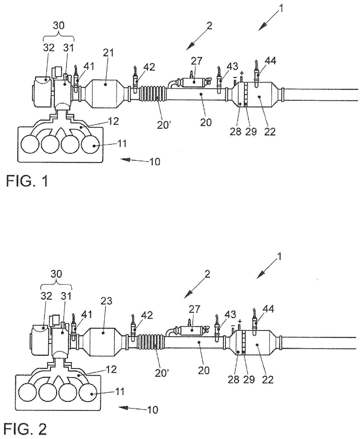
[0045]To achieve a stoichiometric mixed gas with λm=1, in the method the internal combustion engine 10 is operated with a stoichiometric air-fuel mixture of λe=1 (setpoint variable), and the burner 27 is operated with a stoichiometric air-fuel mixture of Ab=1 (setpoint variable). In this way, both exhaust emission control devices 21, 22 are acted on with a stoichiometric exhaust gas, so that they both deliver optimal conversion power immediately after being activated. The internal combustion engine air-fuel mixture λe is regulated via a first lambda control loop by means of the first lambda sensor 41. The air-fuel mixture λb of the burner 27 is regulated via a second, separate lambda control loop by means of the third (or fourth) lambda sensor 42 and 43 (or 44).

[0046]According to a second embodiment of the method, the internal combustion engine 10 is operated slightly rich, for example with λe=0.9, and the burner 27 is operated slightly lean, in such a way that the mixed gas enterin...

second embodiment

[0047]FIG. 2 shows a vehicle 1 having an internal combustion engine 10 and an exhaust gas system 2 connected thereto according to the invention, wherein identical components are denoted by the same reference numerals as in FIG. 1 and are not explained again. The exhaust gas system 2 shown in FIG. 2 differs from FIG. 1 in that the first exhaust emission control device is designed as a four-way catalytic converter 23. This involves a particulate filter, in particular a gasoline engine particulate filter, for mechanical retention of particulate exhaust gas components; the filter substrate of the four-way catalytic converter has a three-way catalytic coating. In this way, the four-way catalytic converter 23 is able to reduce the four exhaust gas components comprising unburned hydrocarbons HC, carbon monoxide CO, nitrogen oxides NOx, and particulate emissions in the exhaust gas.

third embodiment

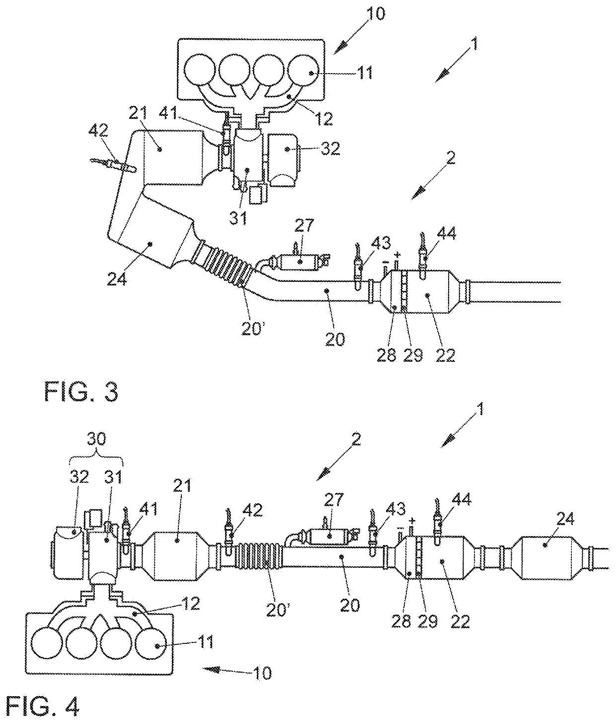
[0048]FIG. 3 shows a vehicle 1 having an internal combustion engine 10 and an exhaust gas system 2 connected thereto according to the invention, wherein identical components are denoted by the same reference numerals as in FIG. 1 and are not explained again. The exhaust gas system 2 shown in FIG. 3 differs from FIG. 1 in that a gasoline engine particulate filter 24 close to the engine is connected downstream from the first exhaust emission control device 21 (three-way catalytic converter), wherein the three-way catalytic converter 21 and the gasoline engine particulate filter 24 are in particular situated on a shared catalytic converter housing. The three-way catalytic converter 21 essentially corresponds to that from FIG. 1. The gasoline engine particulate filter 24 is strictly a particulate filter for mechanical retention of particulate exhaust gas components, without a catalytic coating. In this way, the combination of the first exhaust emission control device 21 and the particul...


PUM


Abstract

An exhaust gas system for an internal combustion engine, comprising a first exhaust emission control device close to the engine and a second exhaust emission control device remote from the engine. The second exhaust emission control device is heatable by a combination of an upstream burner and an electric heating device. For heating the exhaust emission control devices after an engine start, the internal combustion engine is operated with at least one engine-internal measure for raising the exhaust gas temperature, and the burner and the electric heating device are activated at the same time or offset in time for heating the second exhaust emission control device. A mixed gas entering the second exhaust emission control device is set to a stoichiometric lambda value. The invention allows accelerated heating of the exhaust emission control devices, and thus, a reduction in starting emissions.

Description

CROSS REFERENCE TO RELATED APPLICATION[0001]This application claims priority from German Patent Application No. 10 2019 101 394.1, filed Jan. 21, 2019, the contents of which are incorporated herein by reference.FIELD OF THE INVENTION[0002]The invention relates to an exhaust gas system for an internal combustion engine and a method for operating the exhaust gas system, when a low-temperature state is present, for heating exhaust emission control devices of the exhaust gas system.BACKGROUND OF THE INVENTION[0003]Catalytic exhaust emission control devices, which are used in exhaust gas systems of internal combustion engines in vehicles, require an operating temperature in order to be effective. The operating temperature is characterized in particular by a catalytic converter-specific light-off temperature, which is defined as the temperature above which 50% of the incoming emissions are converted. Since catalytic exhaust emission control devices generally have not yet reached their lig...

Claims


Application Information

Patent Timeline
IPC IPC(8): F01N3/027B01D53/94F01N3/20F01N11/00
CPCF01N2250/06F01N11/002F01N2240/14B01D53/9445F01N3/2033F01N3/027F01N2240/16F01N3/2013F01N3/025F01N3/28F01N9/00F01N3/2066F01N3/101F01N3/103F01N3/106F01N3/0253F01N13/0093F01N2340/02
Inventor KAACK, MICHAELPAUKNER, STEFANBARON VON CEUMERN-LINDENSTJERNA, FALK-CHRISTIANBOZALP, TOLGA
Owner VOLKSWAGEN AG
Why Eureka
Try Eureka