Method for removing nitrogen oxides and particulates from the lean exhaust gas of an internal combustion engine and exhaust gas emission system

Inactive Publication Date: 2005-09-06
UMICORE AG & CO KG +1
View PDF11 Cites 36 Cited by
  • Summary
  • Abstract
  • Description
  • Claims
  • Application Information

AI Technical Summary

Benefits of technology

[0023]The above and other objects of the present invention can be achieved by a method comprising in a first cycle, passing the exhaust gas stream over a nitrogen oxide storage catalyst and a particulate filter, and adsorbing nitrogen oxides and sulfur oxides by the storage catalyst under lean exhaust gas conditions, depositing the particulates on the particulate filter, and periodically denitr

Problems solved by technology

This first cycle consisting of storage an

Method used


Image

  • Method for removing nitrogen oxides and particulates from the lean exhaust gas of an internal combustion engine and exhaust gas emission system
  • Method for removing nitrogen oxides and particulates from the lean exhaust gas of an internal combustion engine and exhaust gas emission system
  • Method for removing nitrogen oxides and particulates from the lean exhaust gas of an internal combustion engine and exhaust gas emission system

Examples


second embodiment

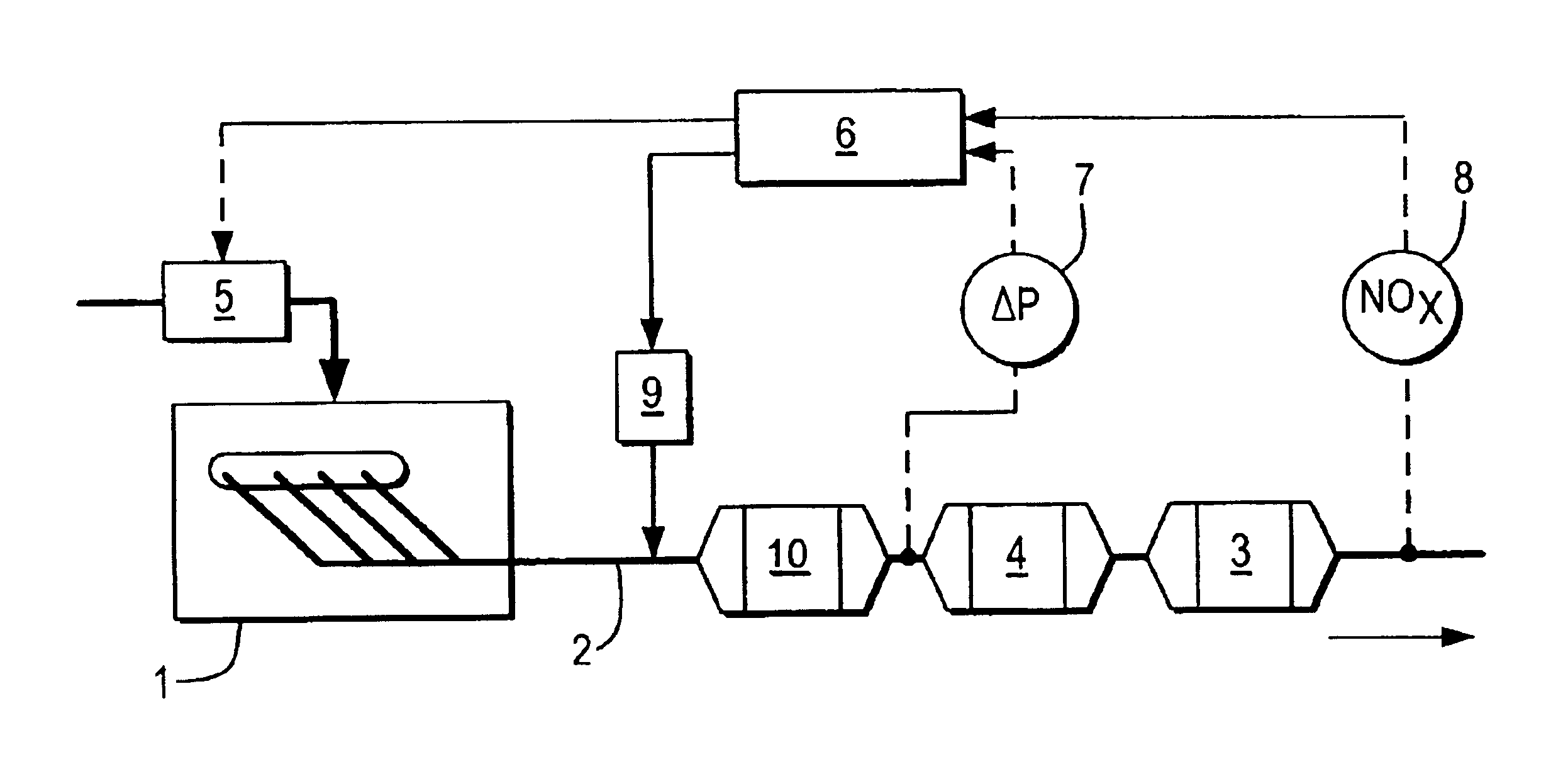
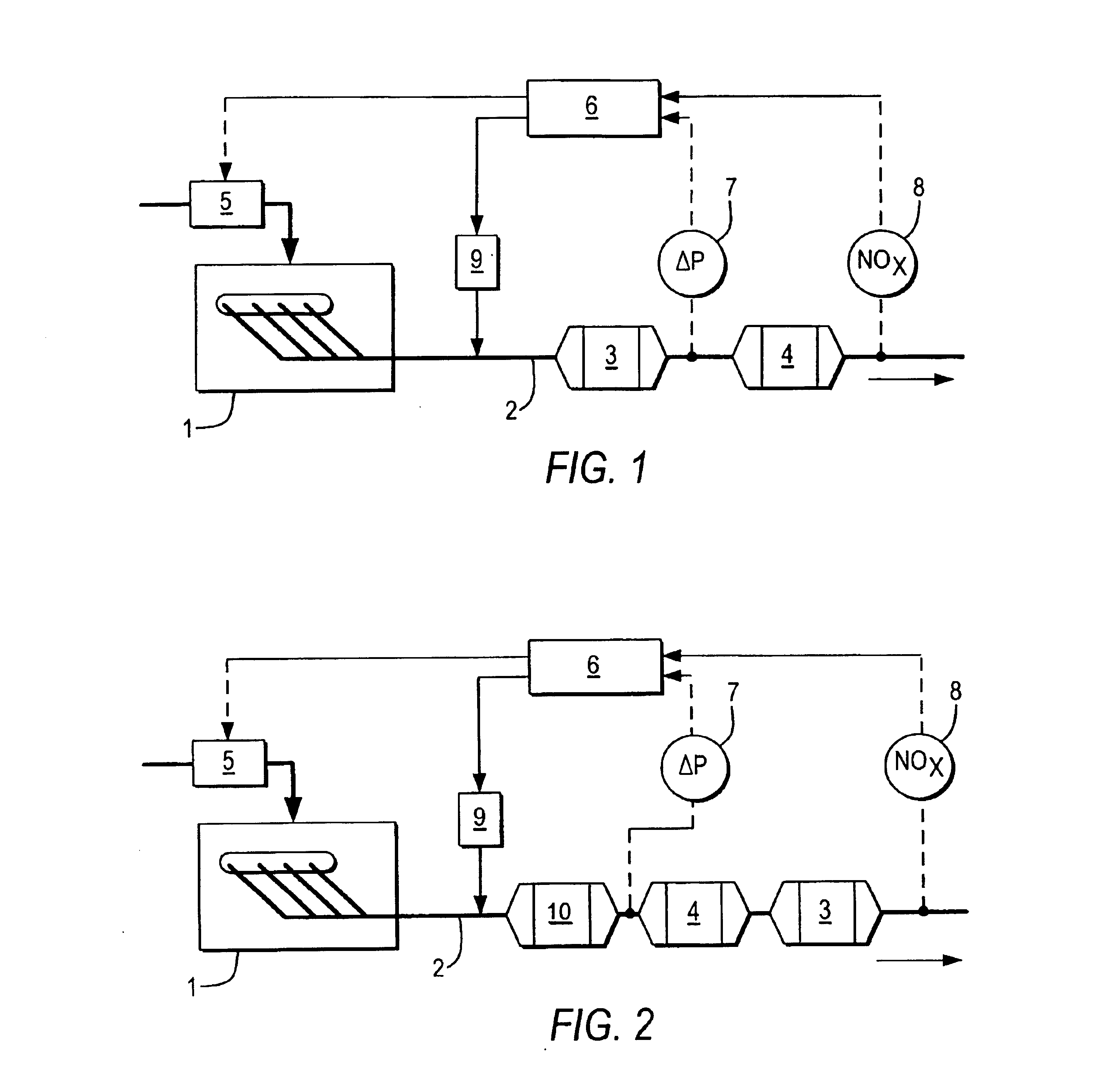
[0056]The arrangement of FIG. 2 is suitable for conducting the method in accordance with the invention. The nitrogen oxide storage catalyst here is arranged after the particulate filter. Now there is an oxidation catalyst (10) in front of the particulate filter, on which the hydrocarbons are burned to increase the exhaust gas temperature for regeneration of the particulate filter.

third embodiment

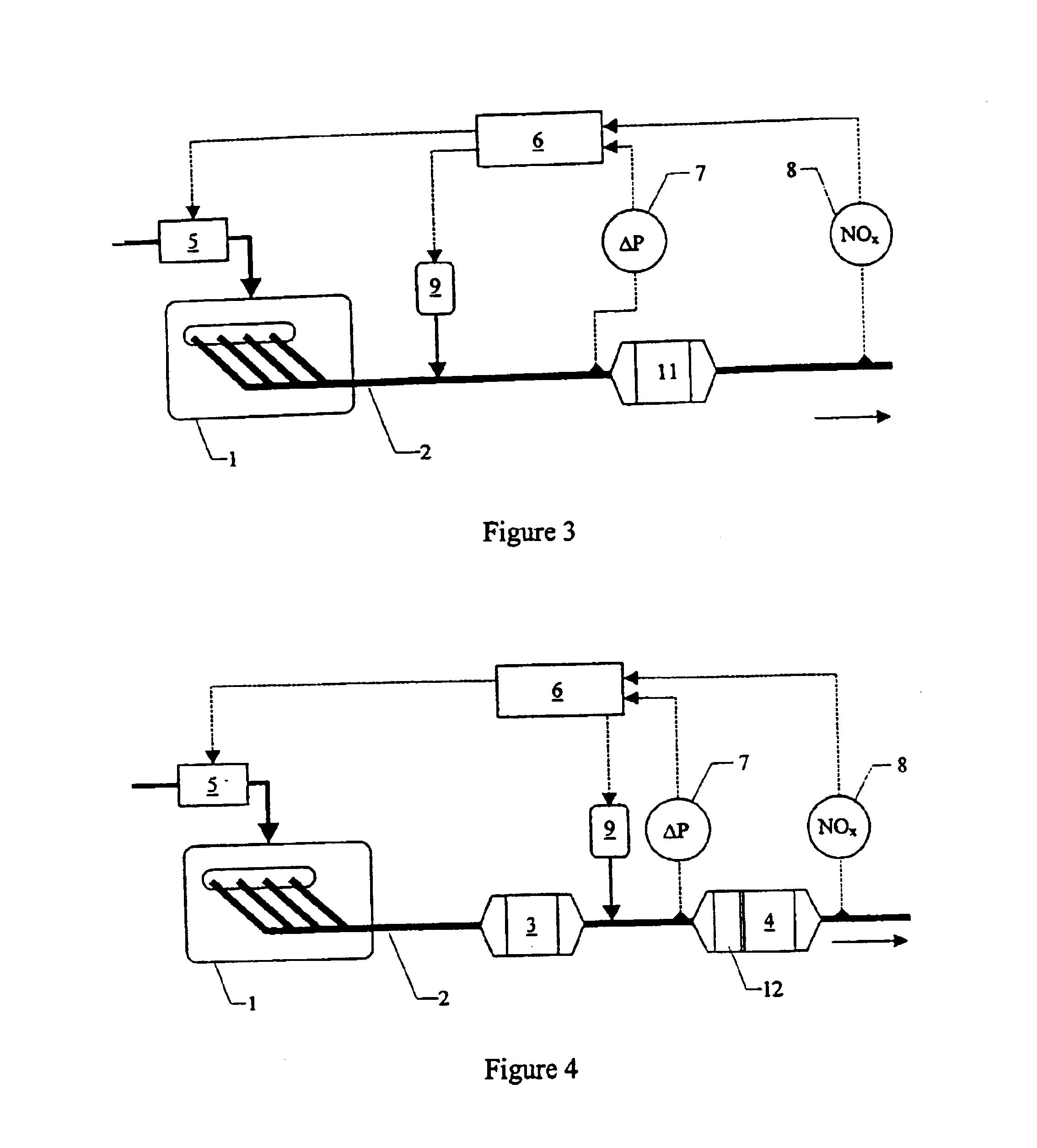
[0057]The arrangement of FIG. 3 is suitable for conducting the process in accordance with a It illustrates a coated particulate filter (11) that is either coated on the inlet and outlet sides with a nitrogen oxide storage catalyst or that has a particulate ignition coating on the inlet side and the nitrogen oxides storage catalyst on the outlet side. As another alternative the particulate filter can be provided on the inlet side with an oxidation catalyst and on the outlet side with the nitrogen oxide storage catalyst.

fourth embodiment

[0058]FIG. 4 shows an arrangement for conducting the invention. In this embodiment an oxidation catalyst (12) is connected in the exhaust gas stream immediately in front of the particulate filter. There is also the possibility of applying this oxidation catalyst as a coating on the inlet side of the particulate filter.


PUM

PropertyMeasurementUnit
Temperatureaaaaaaaaaa
Concentrationaaaaaaaaaa
Ratioaaaaaaaaaa

Abstract

A method for removing nitrogen oxides and particulate matter from the lean exhaust gas of a combustion engine that also contains low concentrations of sulfur oxides. The exhaust gas stream is passed over a nitrogen oxide storage catalyst and a particulate filter, where nitrogen oxides and sulfur oxides are adsorbed by the storage catalyst under lean exhaust gas conditions and the particulate matter is deposited on the particulate filter. The storage catalyst is in a first cycle is periodically denitrated by enriching the exhaust gas regeneration of the particulate filter. Desulfurization of the nitrogen oxide storage catalyst is carried out in a second cycle by raising the temperature of the lean exhaust gas to a value at which the particulate matter combustion on the particulate filter is initiated and then the storage catalyst can be desulfurized by enriching the exhaust gas.

Description

[0001]The present invention relates to a method for removing nitrogen oxides and particulates matter from the lean exhaust gas of a combustion engine that also contains small concentrations of sulfur oxides.[0002]Combustion engines with lean exhaust gas are diesel engines and gasoline engines operated with lean air / fuel mixtures, the so-called lean engines. Important pollutants in the exhaust gas of these engines include carbon monoxide CO, unburned hydrocarbons HC, nitrogen oxides NOx and particulate matter, as well as sulfur oxides SOx that come from the sulfur in the fuel and lubricating oils. In contrast to the exhaust gas of stoichiometrically operated gasoline engines, this exhaust gas contains a high percentage of oxygen. The air ratio λ in the exhaust gas of these engines is usually in the range between 1.3 and 2.[0003]The air ratio λ is the air / fuel ratio normalized to stoichiometric conditions. The air / fuel ratio indicates how many kilograms of air are needed for complete ...

Claims


Application Information

Patent Timeline
IPC IPC(8): B01D53/94F01N3/023F01N3/08F02D41/02F02D41/40F01N7/02F01N7/00F01N3/02B01D46/42B01D53/86B01D53/96F01N3/025F01N3/035F01N3/20F01N3/24F01N3/28F01N9/00F01N13/02F02D41/04
CPCB01D53/9431B01D53/96F01N3/023F01N3/0253F01N3/0821F01N3/0842F01N3/0871F01N3/0885F02D41/0275F02D41/028F02D41/029F02D41/1463F02D41/405F01N13/009F01N13/0097B01D53/9477B01D2255/91B01D2255/915B01D2258/012F01N3/035F01N3/0814F01N3/28F01N9/002F01N2250/02F01N2250/12F01N2250/14F01N2260/04F01N2430/06F01N2430/085F01N2510/065F01N2560/026F01N2570/04F01N2570/14F01N2610/03Y02T10/44Y02A50/20Y02T10/40
Inventor HOFFMANN, MICHAELKLEIN, HARALDKREUZER, THOMASSCHAFER-SINDLINGER, ADOLF
Owner UMICORE AG & CO KG
Why Eureka
Try Eureka