Distributing Power in Systems Having a Composite Structure

a technology of composite structure and distribution system, which is applied in the direction of electrical devices, aircraft static dischargers, contact material materials, etc., can solve the problems of undesirable temperature change that results from passing current from the bolt to the fiber, the significant weight and complexity of the power distribution system of a large commercial aircraft, and the inability to meet the requirements of the system

Active Publication Date: 2010-08-26
THE BOEING CO
View PDF3 Cites 24 Cited by
  • Summary
  • Abstract
  • Description
  • Claims
  • Application Information

AI Technical Summary

Problems solved by technology

Power distribution systems can add significant weight and complexity to any system.
For example, the power distribution system of a large commercial aircraft may be a significant weight burden for the aircraft.
In any case, for aircraft and other vehicles, wire routing can be a significant concern due to issues such as shielding the wires to avoid chafing and routing the wires in safe locations.
The current density associated with the bolt may be high enough that a temperature change that results from passing current from the bolt to the fibers becomes undesirable.
Approaching or exceeding the glass transition temperature may cause the composite member to soften and would be undesirable.
Additionally, the illustrations are merely representational and may not be drawn to scale.

Method used


Image

  • Distributing Power in Systems Having a Composite Structure
  • Distributing Power in Systems Having a Composite Structure
  • Distributing Power in Systems Having a Composite Structure

Examples


first embodiment

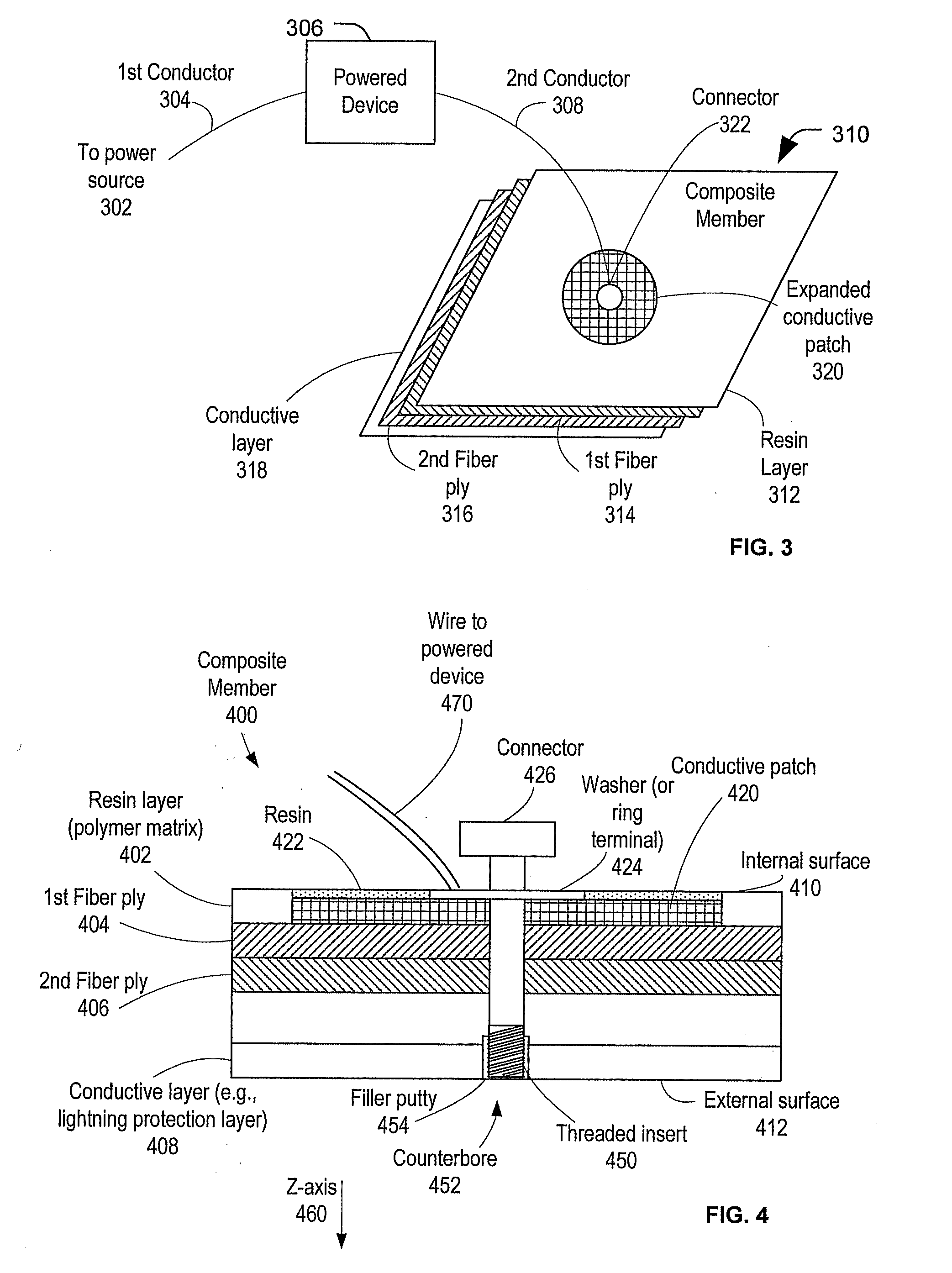
[0020]FIG. 3 is an illustration of a system to distribute power. The system includes a powered device 306 coupled via a first conductor 304 to a power source 302. The powered device 306 is also coupled to a connector 322 supported by a conductive patch 320 on a composite member 310 via a second conductor 308. In a particular embodiment, the composite member 310 may be a panel or other member of an aircraft, such as the aircraft 200 of FIG. 2. In this embodiment, the powered device 306 may be an aircraft component that receives power from the power source 302 via the first conductor 304.

[0021]In a particular embodiment, the composite member 310 includes a plurality of fibers bound by one or more resins. For example, the composite member 310 may include a carbon fiber reinforced polymer (CFRP) member, a composite of non-carbon fibers (e.g., boron fibers, metal fibers, etc.) bound by a resin or other continuous medium. For purposes of illustration in FIG. 3, the composite member 310 is...

second embodiment

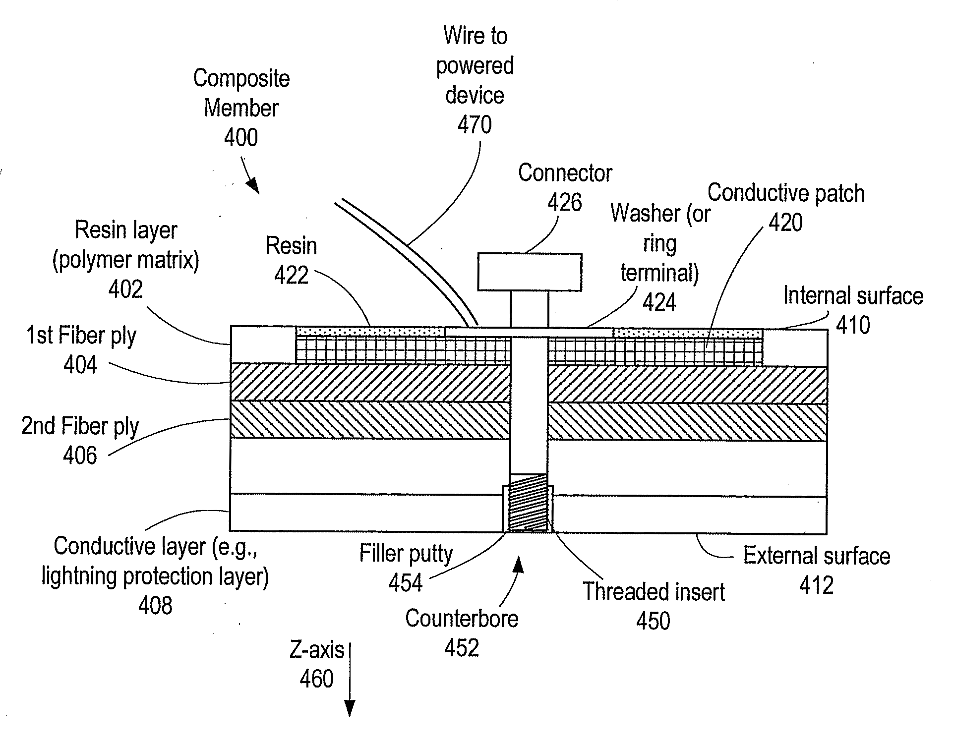
[0027]FIG. 4 is an illustration of a system to distribute power. The system illustrated in FIG. 4 includes a composite member 400. In a particular embodiment, the composite member 400 includes a skin or structural member of a vehicle having a composite construction. For example, the composite member 400 may include a panel, a structural member, or a fuselage segment of an aircraft, such as the aircraft 200 of FIG. 2.

[0028]The composite member 400 may include a plurality of fibers, such as a first fiber ply 404 and a second fiber ply 406, bound by a polymer matrix. In FIG. 4, the polymer matrix is illustrated as a resin layer 402; however, the polymer matrix may be at a surface or surfaces of the composite member, intermixed with the plurality of fibers, at other locations of the composite member 400, or any combination thereof. In a particular embodiment, the polymer matrix is a continuous medium and the fibers of the fiber plies 404, 406 are a discontinuous medium of the composite ...


PUM

PropertyMeasurementUnit
temperatureaaaaaaaaaa
operational temperatureaaaaaaaaaa

Abstract

Systems and methods to distribute power in a system having a composite structure are provided. A particular aircraft includes a fuselage having a composite skin. The composite skin includes a first resin and a plurality of fibers. The fuselage also includes an expanded conductive patch bonded to an interior surface of the composite skin by a second resin. The expanded conductive patch is in electrical contact with the plurality of fibers. The fuselage also includes a connector in electrical contact with the expanded conductive patch.

Description

FIELD OF THE DISCLOSURE[0001]The present disclosure is generally related to distributing power in systems having a composite structure.BACKGROUND[0002]Power distribution systems can add significant weight and complexity to any system. For example, the power distribution system of a large commercial aircraft may be a significant weight burden for the aircraft. Power distribution systems typically use at least two wires to supply power from a power source to a powered device: a first wire (or a powered wire) to send current from the power source to the powered device and a second wire (or a return wire) to receive return current from the powered device at the power source. Thus, the power distribution system includes the weight of both the power wire and the return wire. Besides the issue of the weight of the two or more wires, using two or more wires to distribute power has the additional concern of routing the wires. In an aircraft or other vehicle where conductive metals are the pr...

Claims


Application Information

Patent Timeline
Patent Type & Authority Applications(United States)
IPC IPC(8): B64D45/02B32B15/04B64C1/00B64C1/06H02G3/00
CPCB64C1/068B64C2001/0072B64D2221/00Y10T29/49117Y02T50/433Y10T29/4997H01R4/64Y02T50/40Y10T428/31678
Inventor ROBB, ANDREW M.
Owner THE BOEING CO
Why Eureka
Try Eureka