Over-current protection circuit and motor controller comprising the same

a protection circuit and motor controller technology, applied in the direction of electrical equipment, lighting device details, lighting and heating equipment, etc., can solve the problems of high cost, high cost, high cost, etc., and achieve the effect of simple structure, high reliability and small siz

Inactive Publication Date: 2010-08-26
ZHONGSHAN BROAD OCEAN
View PDF0 Cites 9 Cited by
  • Summary
  • Abstract
  • Description
  • Claims
  • Application Information

AI Technical Summary

Benefits of technology

[0023]Advantages of the motor controller of the invention comprise: 1) it features a wide over-current protection range from several microampere grade to tens ampere; 2) it has a small size, a simple structure, high reliability, and low cost; 3) it features less heat radiation, low temperature rise, good adaptability and improves reliability of the motor controller.

Problems solved by technology

However, there are several problems with the over-current protection circuit: the fuse cannot be reused, the thermistor and the switch are expensive and unsuitable for circuits with a small or large current, and the transistor features a complex structure and high cost, and a limited over-current protection range.

Method used


Image

  • Over-current protection circuit and motor controller comprising the same
  • Over-current protection circuit and motor controller comprising the same
  • Over-current protection circuit and motor controller comprising the same

Examples


Embodiment Construction

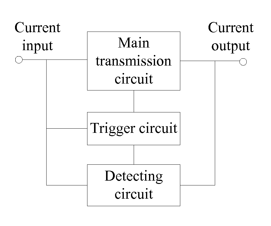
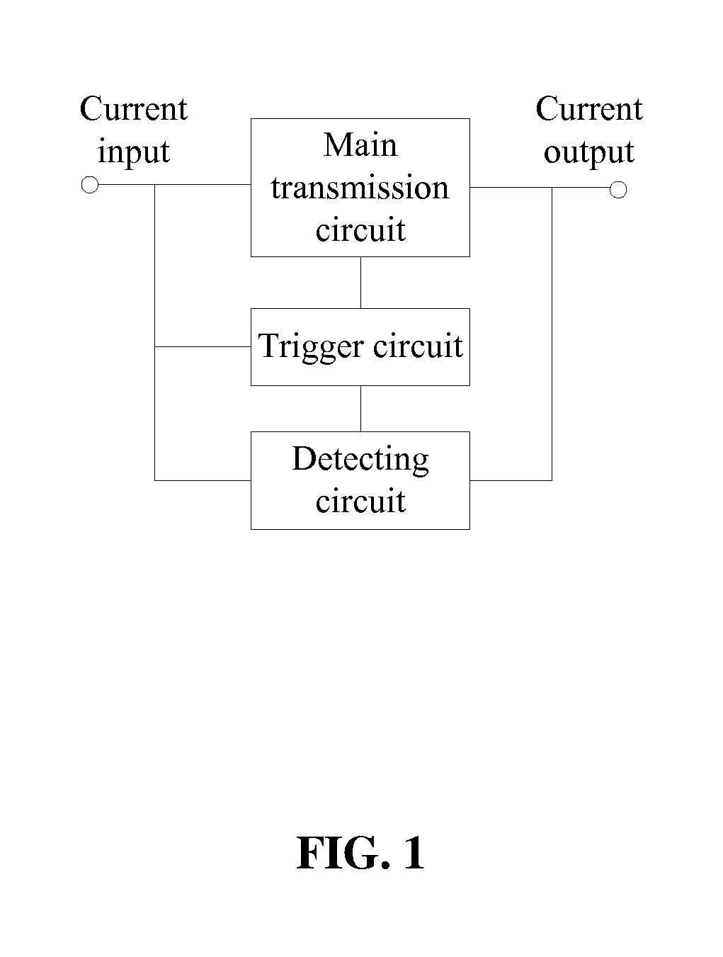
[0030]As shown in FIGS. 1 and 2, an over-current protection circuit of the invention comprises a main transmission circuit, a trigger circuit, and a detecting circuit.

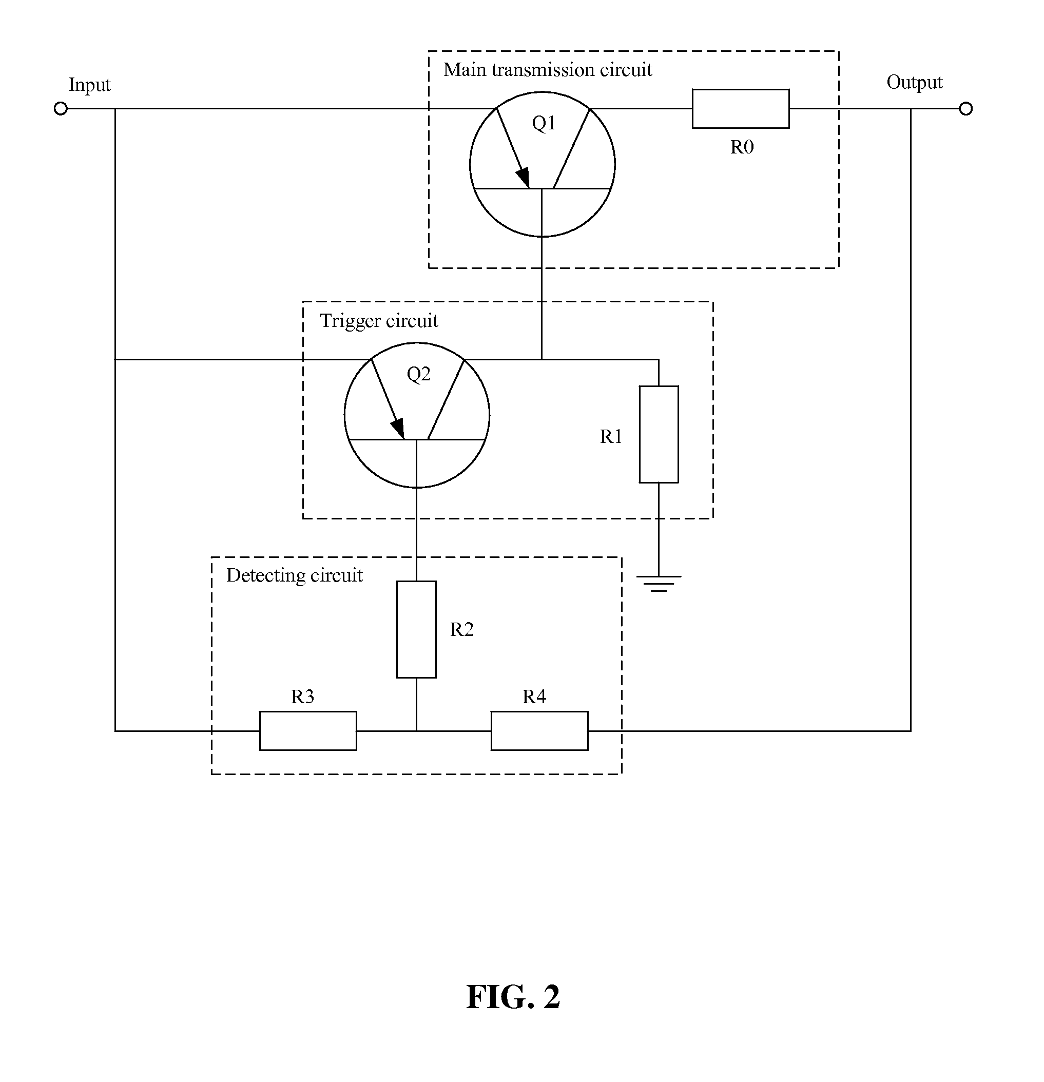
[0031]The main transmission circuit comprises a first triode Q1 and a first resistor R0. One end of the first resistor R0 is connected to an emitting electrode of the first triode Q1, the other end of the first resistor R0 is connected to a current output, and the collecting electrode of the first triode Q1 is connected to a current input. In this embodiment, the first resistor R0 is a variable resistor.

[0032]The trigger circuit comprises a second triode Q2 and a second resistor R1. One end of the first resistor R1 is connected to a collecting electrode of the second triode Q2, and the other end of the first resistor R1 is connected to the ground. An emitting electrode of the second triode Q2 is connected to the current input, and the collecting electrode of the second triode Q2 is connected to a base electrode of the ...


PUM


Abstract

An over-current protection circuit, has a main transmission circuit including at least a first triode and a first resistor, a trigger circuit including a second triode and a second resistor, and a detecting circuit having an input terminal and an output terminal. One end of the first resistor is connected to one end of a collecting electrode and an emitting electrode of the first triode. The other end of the first resistor is connected to a current output. The other end of the collecting electrode and the emitting electrode of the first triode is connected to a current input. One end of the second resistor is connected to a collecting electrode of the second triode. The other end of the second resistor is connected to the ground. An emitting electrode of the second triode is connected to the current input. The collecting electrode of the second triode is connected to a base electrode of the first triode. The input terminal of the detecting circuit is connected to the current output whereby extracting a detecting signal therefrom. The output terminal of the detecting circuit is connected to a base electrode of the second triode

Description

CROSS-REFERENCE TO RELATED APPLICATIONS[0001]Pursuant to 35 U.S.C. §119 and the Paris Convention Treaty, this application claims the benefit of Chinese Patent Application No. 200920051889.0 filed on Feb. 24, 2009, the contents of which are incorporated herein by reference.BACKGROUND OF THE INVENTION[0002]1. Field of the Invention[0003]The invention relates to an over-current protection circuit and a motor controller comprising the same.[0004]2. Description of the Related Art[0005]Over-current protection circuits are widely used in current DC power supplies. Conventional over-current protection circuits use fuses, positive temperature coefficient (PTC) thermistors, switches or transistors. However, there are several problems with the over-current protection circuit: the fuse cannot be reused, the thermistor and the switch are expensive and unsuitable for circuits with a small or large current, and the transistor features a complex structure and high cost, and a limited over-current p...

Claims


Application Information

Patent Timeline
Patent Type & Authority Applications(United States)
IPC IPC(8): H02H7/085
CPCH02H7/0833H02H3/025H02H3/087
Inventor ZHAO, YONGZHANG, JUNQIANGLIU, DAWEITANG, SONGFA
Owner ZHONGSHAN BROAD OCEAN
Why Eureka
Try Eureka