Transonic blade

a transonic blade and blade technology, applied in the direction of wind motors with parallel air flow, wind motors with perpendicular air flow, liquid fuel engine components, etc., can solve the problems of increasing local stress, insufficient discussion of the strength of the transonic blade with respect to the modification of the stacking line, etc., to reduce local stress and reduce shock loss

Active Publication Date: 2010-08-26
MITSUBISHI POWER LTD
View PDF13 Cites 49 Cited by
  • Summary
  • Abstract
  • Description
  • Claims
  • Application Information

AI Technical Summary

Benefits of technology

[0007]The transonic blades described in JP-7-224794-A and JP-2008-115736-A are formed such that the overall gravity center position is shifted toward the upstream side in order to reduce various losses due to a shock wave at the tip cross-sectional surface. The blade whose gravity center position is shifted as described above has a problem of increasing local stress in the vicinity of the leading edge of the hub cross-sectional surface compared with a transonic blade having a stacking line perpendicular to a vertical direction.
[0008]Accordingly, it is an object of the present invention to provide a transonic blade that reduces local stress at a hub cross-sectional surface while achieving a reduction in shock loss at a tip cross-sectional surface.
[0010]The present invention can provide a transonic blade that can reduce local stress at the hub cross-sectional surface while achieving a reduction in shock loss resulting from a shock wave on the tip cross-sectional surface.

Problems solved by technology

However, JP-7-224794-A and JP-2008-115736-A do not sufficiently discuss the strength of the transonic blade with respect to the modification of the stacking line.
The blade whose gravity center position is shifted as described above has a problem of increasing local stress in the vicinity of the leading edge of the hub cross-sectional surface compared with a transonic blade having a stacking line perpendicular to a vertical direction.

Method used


Image

  • Transonic blade
  • Transonic blade
  • Transonic blade

Examples


first embodiment

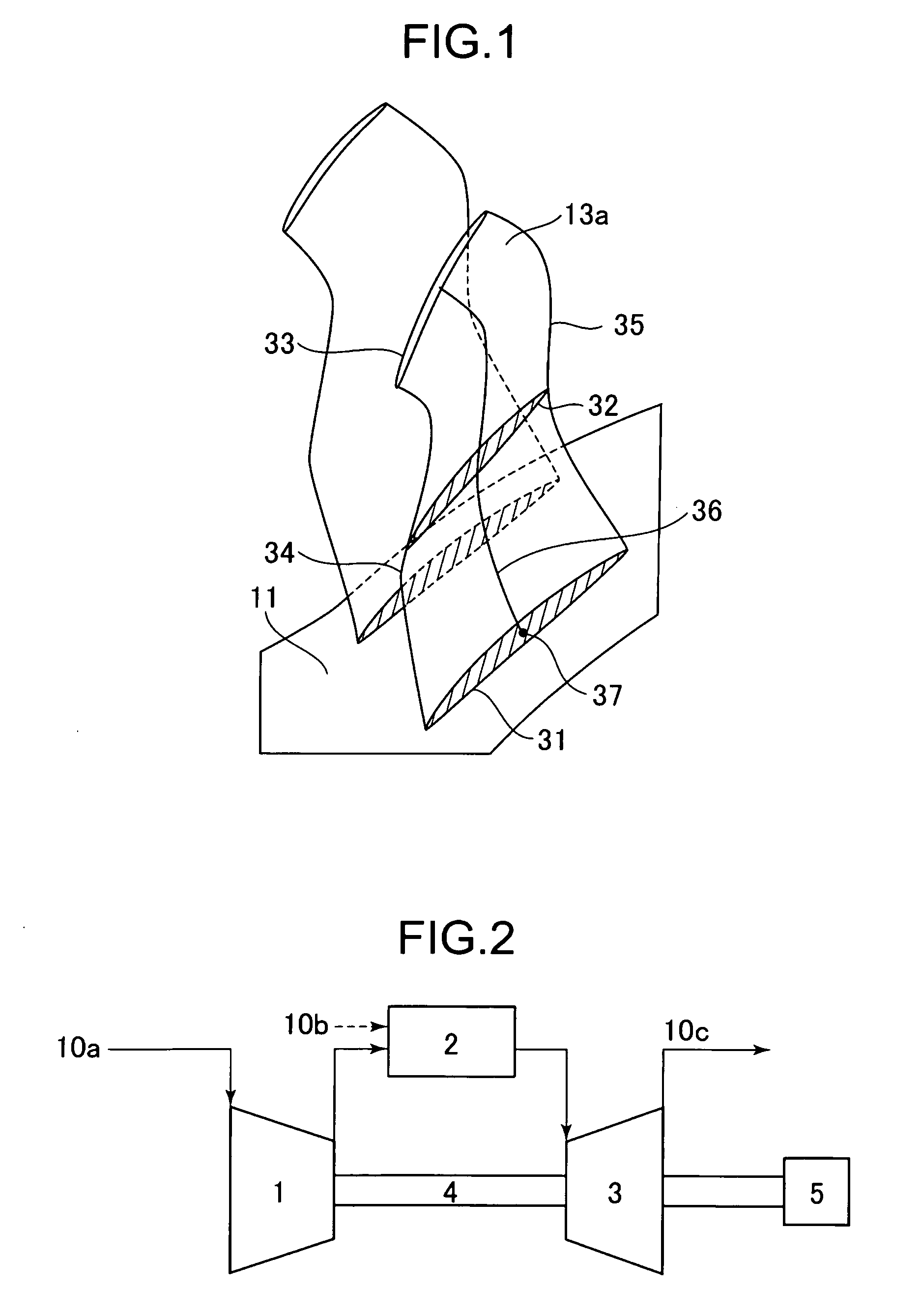
[0036]FIG. 2 is a cycle configuration diagram of an axial-flow rotating machine into which a transonic blade of a first embodiment is built. The axial-flow rotating machine is described taking a gas turbine compressor as an example.

[0037]A description is first given of an outline of a cycle. Working fluid 10a first flows into an axial-flow compressor 1. The working fluid 10a compressed by the compressor 1 flows into a combustor 2, in which the compressed working fluid is mixed and burned together with fuel 10b injected thereinto to produce high temperature high pressure combustion gas 10c. The high temperature high pressure combustion gas 10c flows into a turbine 3. The combustion gas 10c flowing into the turbine 3 rotates a shaft 4 to drive a generator 5 for electric power generation.

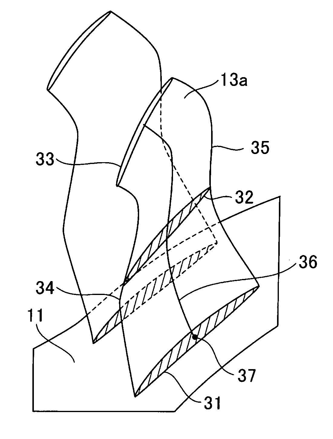
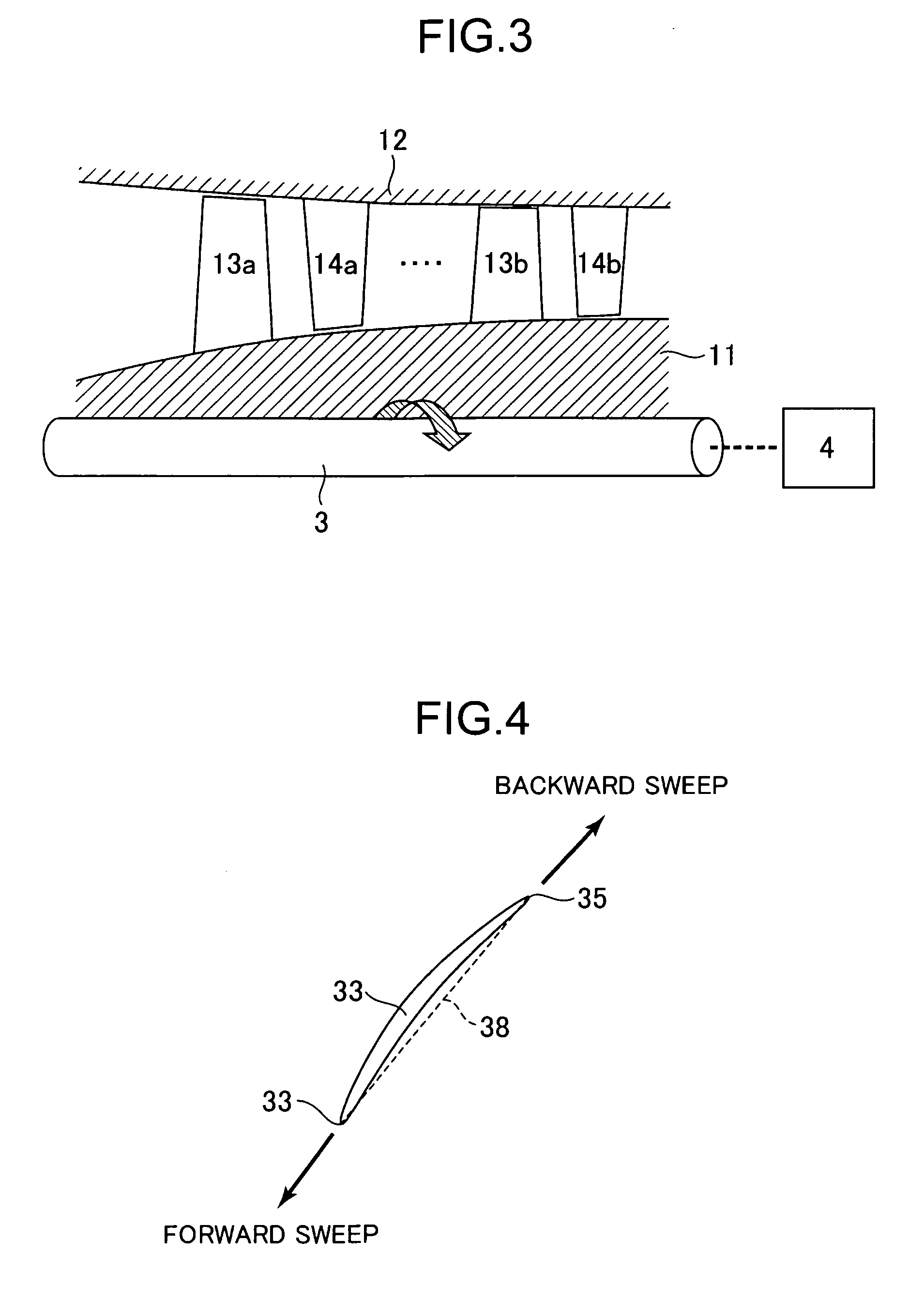
[0038]FIG. 3 is a cross-sectional view of the axial-flow compressor 1 taken along a meridional plane. Referring to FIG. 3, the compressor 1 is configured to include a rotor 11 or a rotating shaft; a ca...

second embodiment

[0053]FIG. 15 is a perspective view of a rotor blade 13a according to a second embodiment. The rotor blade 13a of the second embodiment is different from the rotor blade of the first embodiment in that a stacking line extending from a hub cross-sectional surface 31 to a mean cross-sectional surface 32 is a straight line and a tip cross-sectional surface is located on the most upstream side. Incidentally, the same elements as in FIG. 1 are denoted with like reference numerals and their detailed descriptions are omitted.

[0054]Characteristics of the rotor blade 13a of the present embodiment are described with reference to FIG. 16. FIG. 16 illustrates a comparison between the stacking line of the present embodiment and that of the first embodiment. The stacking line 36 of the present embodiment is a straight line extending from the hub cross-sectional surface 31 to the mean cross-sectional surface 32 and is shaped to protrude toward the downstream side in the main flow direction from th...


PUM


Abstract

A transonic blade is provided that operates in a flow field where flow has a transonic speed or higher in an axial-flow rotating machine and that concurrently achieves a reduction in shock loss and in the local stress of the blade.The transonic blade includes a hub cross-sectional surface joined to a rotating shaft or an outer circumferential side casing of a rotating machine; a tip cross-sectional surface located furthest from the hub cross-sectional surface in a spanwise direction which is a vertical direction of the rotating shaft; a leading edge located on an upstream side; and a trailing edge located on a downstream side. At least a part of a passing working fluid flow has a transonic speed or higher. A portion of a stacking line which is a line connecting together respective gravity centers of cross-sectional surfaces located from the hub cross-sectional surface to the tip cross-sectional surface is located on a downstream side of a stacking center in a flow direction of a working fluid main flow.

Description

BACKGROUND OF THE INVENTION[0001]1. Field of the Invention[0002]The present invention relates to an axial-flow rotating machine provided with a transonic blade used in a flow field where an overall or partial flow has a transonic speed or higher.[0003]2. Description of the Related Art[0004]In the context of increased fuel cost and of the raising of environmental awareness in recent years, the importance of improved efficiency has been raised in axial-flow rotating machines such as industrial gas turbines and jet engines. One of means of improving efficiency in the axial-flow rotating machine is to reduce a blade loss. The blade loss is classified roughly into a profile loss occurring at a cross-sectional surface (airfoil) of a blade in the radial direction of a rotating shaft and the other losses. Examples of the other losses include a shock loss and a secondary loss. The recent axial-flow rotating machines have a large load per one stage and an increased Mach number of working flui...

Claims


Application Information

Patent Timeline
Patent Type & Authority Applications(United States)
IPC IPC(8): F01D5/14
CPCY02T50/673F01D5/141Y02T50/60
Inventor MYOREN, CHIHIROTAKAHASHI, YASUO
Owner MITSUBISHI POWER LTD
Why Eureka
Try Eureka