
Air Outlet Valve As Well As a System and Method for Emergency Ventilation of An Aircraft Cabin

a technology for air outlet valves and aircraft cabins, which is applied in ventilation systems, lighting and heating apparatus, heating types, etc. it can solve the problems of inability to use, inability to direct inability to complete or limit the extent of directing air from the environment, so as to improve the functional properties and increase the volume of airflow

Active Publication Date: 2010-08-26
AIRBUS OPERATIONS GMBH
View PDF10 Cites 18 Cited by
  • Summary
  • Abstract
  • Description
  • Claims
  • Application Information

AI Technical Summary

Benefits of technology

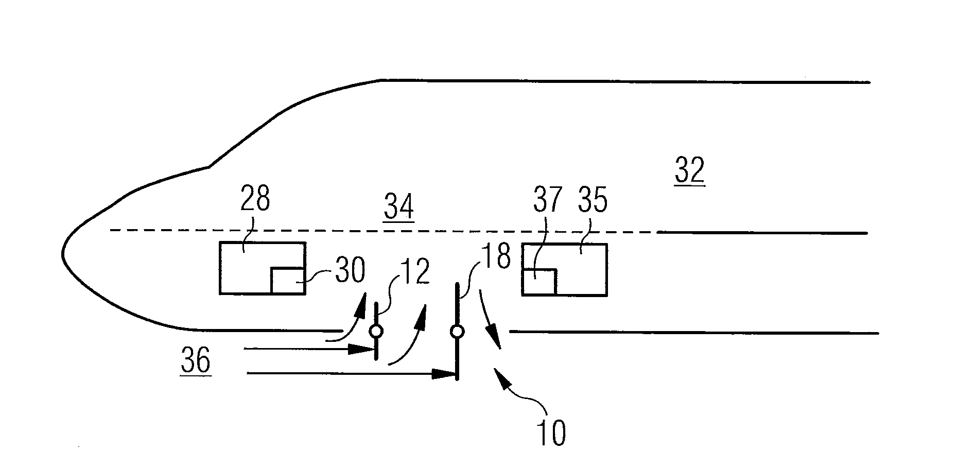
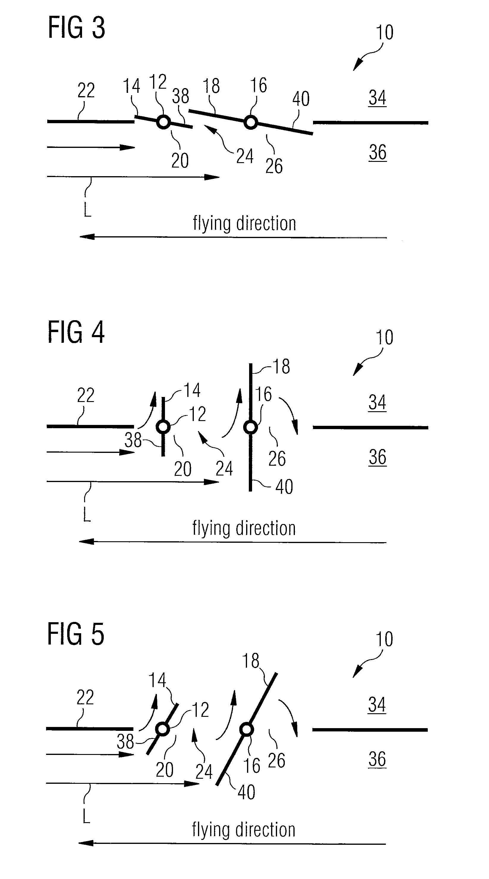
[0016]The design according to the invention of the air outlet valve achieves the effect that in the open state of the valve flaps it is not just at the portion of the nose-side valve flap that projects into the air stream flowing around the aircraft skin during cruising of the aircraft that a ram pressure arises, which in a region of the nose-side air outlet valve aperture portion situated between an—in relation to the air outlet valve—nose-side portion of the aircraft skin and the pivot axis of the nose-side valve flap effects an inflow of air from the environment around the aircraft into the interior of the aircraft. Rather, an additional ram pressure arises also at the portion of the tail-side valve flap that extends beyond the portion of the nose-side valve flap projecting into the air stream flowing around the aircraft skin during cruising of the aircraft into the air stream flowing around the aircraft skin during cruising of the aircraft. The effect of this additional ram pressure is that air may flow from the environment around the aircraft into the interior of the aircraft also in a region of the air outlet valve aperture that is situated between the pivot axes of the valve flaps.
[0021]The nose-side valve flap may be adapted to be positioned at a setting angle greater than 90° relative to the air stream flowing around the aircraft skin during cruising of the aircraft. Alternatively or in addition thereto, the tail-side valve flap may also be adapted to be positioned at a setting angle greater than 90° relative to the air stream flowing around the aircraft skin during cruising of the aircraft. By positioning the valve flaps at a setting angle greater than 90° relative to the air stream flowing around the aircraft skin during cruising of the aircraft, the air inflow from the environment around the aircraft into the interior of the aircraft through the air outlet valve aperture may be intensified compared to an operating state of the air outlet valve, in which the valve flaps are positioned at a setting angle of 90° relative to the air stream flowing around the aircraft skin during cruising of the aircraft.
[0023]In a preferred embodiment of the air outlet valve according to the invention, the tail-side valve flap comprises a cover, which is adapted to close a region of the tail-side air outlet valve aperture portion that is disposed between the pivot axis of the tail-side valve flap and an—in relation to the air outlet valve—tail-side portion of the aircraft skin when the tail-side valve flap is in its open position, in which it opens the tail-side air outlet valve aperture portion. In the region of the tail-side air outlet valve aperture portion that is disposed between the pivot axis of the tail-side valve flap and the—in relation to the air outlet valve—tail-side portion of the aircraft skin, owing to the fact that in this region there is no ram pressure that might lead to an air inflow from the environment around the aircraft into the interior of the aircraft air passes in the open state of the valve flaps from the interior of the aircraft into the environment around the aircraft. With the aid of the cover this undesirable exit of air from the aircraft interior into the environment around the aircraft may be prevented. The air supply into the aircraft cabin during emergency ventilation operation of the aircraft is therefore further improved.
[0026]The cover may for example be controllable by means of a control unit of the cabin pressure control system and / or of the system for emergency ventilation of the aircraft cabin into a desired position, in which it opens or closes the region of the tail-side air outlet valve aperture portion that is disposed between the pivot axis of the tail-side valve flap and the—in relation to the air outlet valve—tail-side portion of the aircraft skin. The control unit may be designed for example in the form of an electronic control unit. Preferably, control of the cover independently of control of the tail-side valve flap is possible.

Problems solved by technology

Known air outlet valves for use in a cabin pressure control system have the drawback that, because of their construction, they are completely incapable or capable only to a limited extent of directing air from the environment around the aircraft into the interior of the aircraft.
For example, a conventional air outlet valve having flaps that are pivotable about pivot axes disposed laterally relative to the flaps cannot be used in a system for emergency ventilation of an aircraft cabin to direct air from the environment around the aircraft into the aircraft cabin.
Such an air outlet valve is therefore also suitable only to a limited extent for use in a system for emergency ventilation of an aircraft cabin.

Method used


Image

  • Air Outlet Valve As Well As a System and Method for Emergency Ventilation of An Aircraft Cabin
  • Air Outlet Valve As Well As a System and Method for Emergency Ventilation of An Aircraft Cabin
  • Air Outlet Valve As Well As a System and Method for Emergency Ventilation of An Aircraft Cabin

Examples


Embodiment Construction

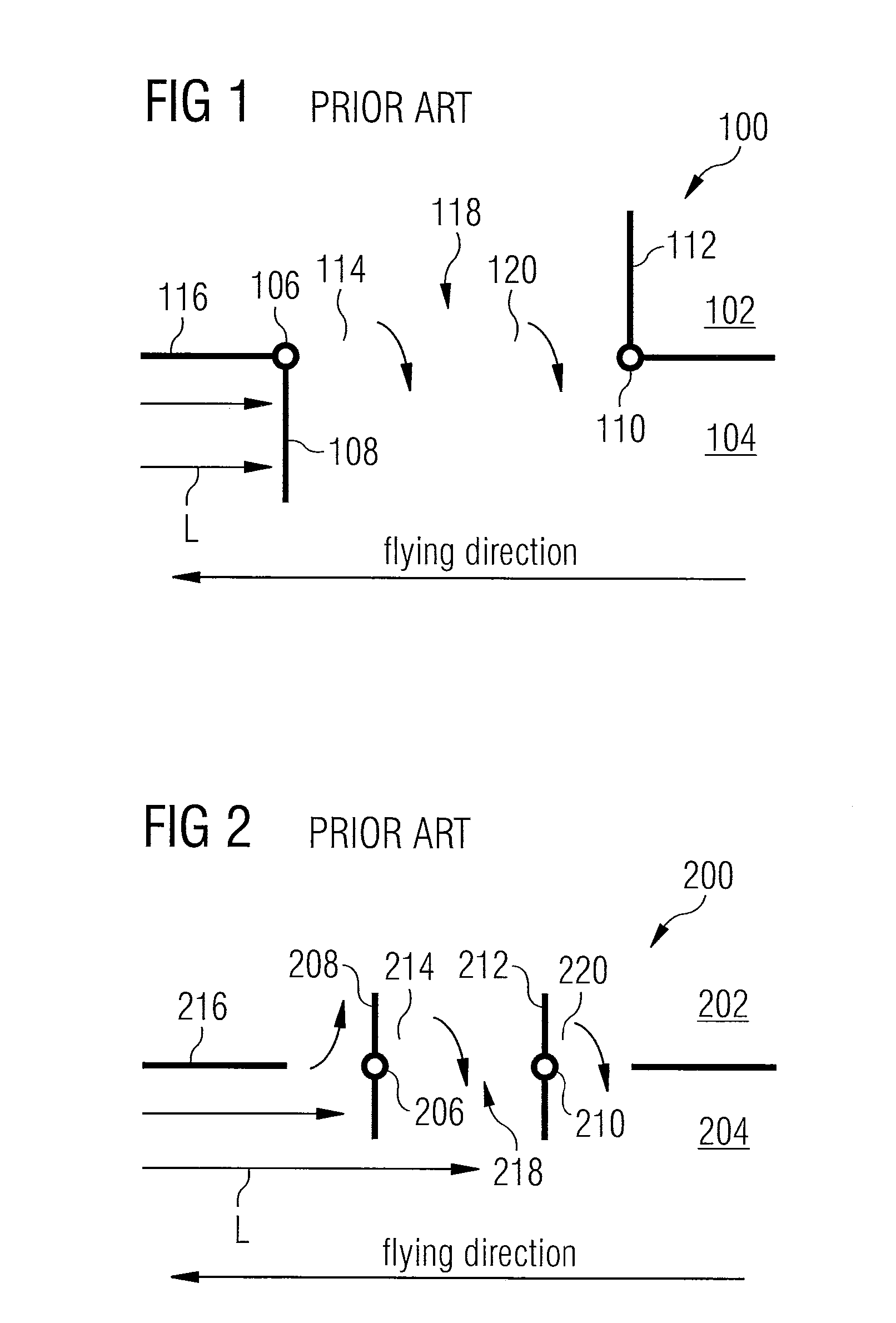
[0044]FIG. 1 shows an air outlet valve 100 known from the prior art that is provided for use in an aircraft. The air outlet valve 100 forms a component of a cabin pressure control system of the aircraft and is used to remove air from an interior 102 of the aircraft into the environment 104 around the aircraft in order to adjust a desired pressure level in an aircraft cabin. The air outlet valve 100 comprises a nose-side valve flap 108 that is pivotable about an axis 106 as well as a tail-side valve flap 112 that is pivotable about an axis 110. The nose-side valve flap 108 is adapted to open or close a nose-side portion 114 of an air outlet valve aperture 118 formed in an aircraft skin 116. In a similar fashion, the tail-side valve flap 112 is adapted to open or close a tail-side portion 120 of the air outlet valve aperture 118 formed in the aircraft skin 116.

[0045]The pivot axes 106, 110 each are disposed laterally relative to the valve flaps 108, 112. In its open state the nose-sid...


PUM


Abstract

An air outlet valve for use in an aircraft is adapted during normal operation of the aircraft as a component of a cabin pressure control system for adjusting a desired pressure level in an aircraft cabin to remove air from an interior of the aircraft into the environment around the aircraft. The air outlet valve is further adapted during emergency ventilation operation of the aircraft as a component of a system for emergency ventilation of the aircraft cabin to introduce air from the environment around the aircraft into the interior of the aircraft. The air outlet valve comprises a nose-side valve flap, which is pivotable about an axis and is adapted to open or close a nose-side portion of an air outlet valve aperture, and a tail-side valve flap, which is pivotable about an axis and is adapted to open or close a tail-side portion of the air outlet valve aperture. A portion of the tail-side valve flap that in the open state of the tail-side valve flap projects into an air stream flowing around an aircraft skin during cruising of the aircraft is greater than a portion of the nose-side valve flap that in the open state of the nose-side valve flap projects into the air stream flowing around the aircraft skin during cruising of the aircraft.

Description

CROSS-REFERENCE TO RELATED APPLICATIONS[0001]This application claims priority to German Application No. 10 2009 010 150.0, filed Feb. 23, 2009 and to U.S. Provisional Application No. 61 / 154,512, filed Feb. 23, 2009.BACKGROUND OF THE INVENTION[0002]1) Field of the Invention[0003]The invention relates to an air outlet valve for use in an aircraft which is adapted during normal operation of the aircraft as a component of a cabin pressure control system for adjusting a desired pressure level in an aircraft cabin to remove air from an interior of the aircraft into the environment around the aircraft, and which is further adapted during emergency ventilation operation of the aircraft, when the aircraft cabin can no longer be supplied with sufficient breathable air by an aircraft air-conditioning system, as a component of a system for emergency ventilation of the aircraft cabin to introduce air from the environment around the aircraft into the interior of the aircraft.[0004]2) Discussion o...

Claims


Application Information

Patent Timeline
Patent Type & Authority Applications(United States)
IPC IPC(8): B64D13/02F24F11/04B64D13/04
CPCB64D13/02B64D13/00
Inventor HEUER, THOMAS
Owner AIRBUS OPERATIONS GMBH
Learn More