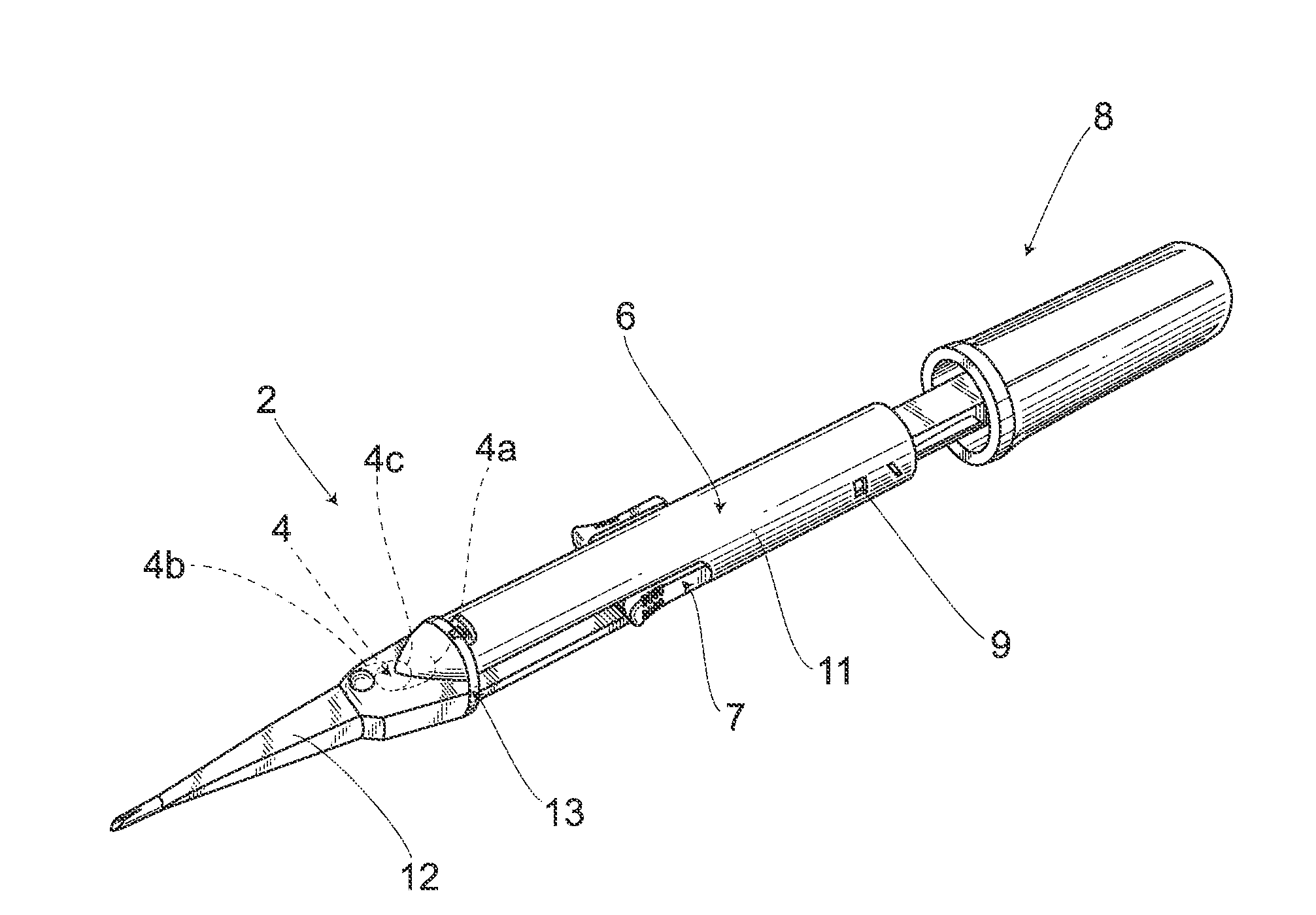
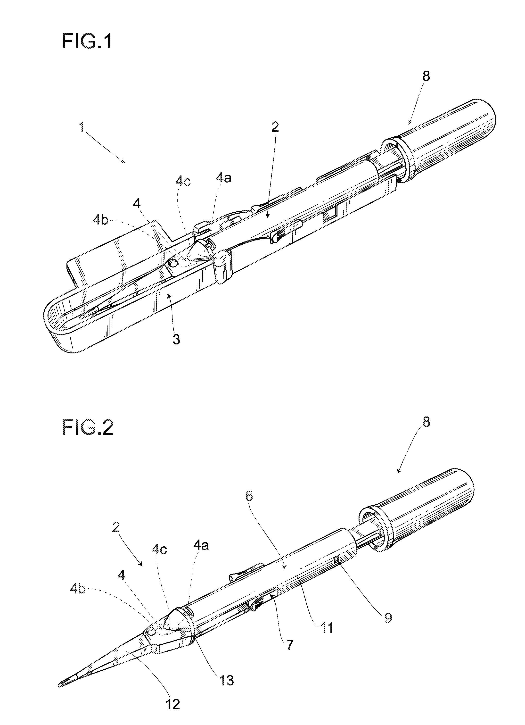
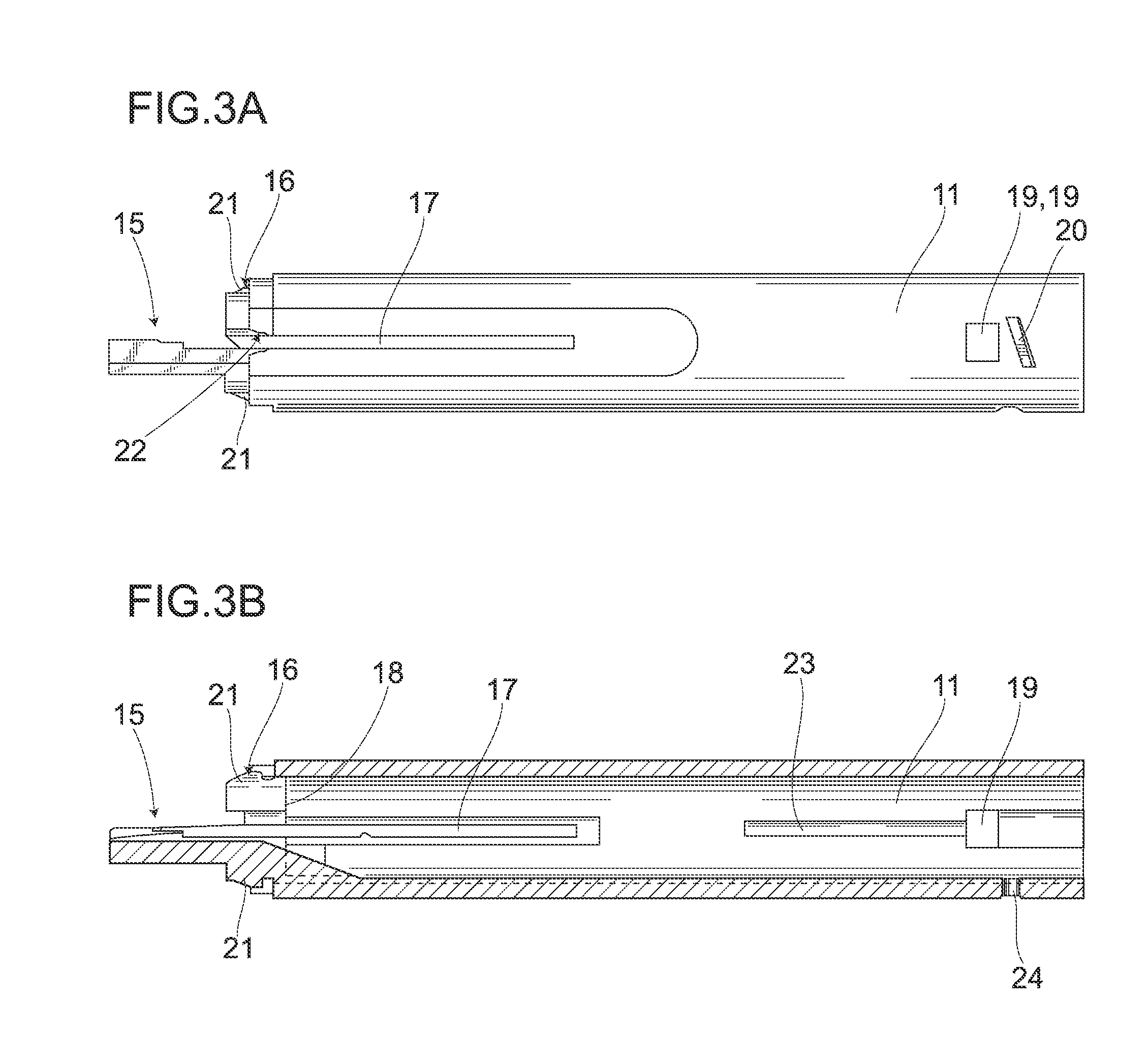
Intraocular Lens Insertion Device

a technology of intraocular lens and plunger, which is applied in the field of intraocular lens insertion device, can solve the problems of reducing the possibility of corneal astigmatism or infection disease after surgery, and it is difficult in some cases to obtain the desired property of the intraocular lens appropriately, so as to prevent the optical part from being damaged and prevent the leading end of the plunger from running

Active Publication Date: 2010-08-26
HOYA CORP
View PDF103 Cites 85 Cited by
  • Summary
  • Abstract
  • Description
  • Claims
  • Application Information

AI Technical Summary

Benefits of technology

[0019]According to the intraocular lens insertion device set forth in the first aspect of the invention, the protrusive part pushes the lens contact part downwardly the intraocular lens by the deformation of the intraocular lens, a possibility that the intraocular lens is damaged is further reduced, and the intraocular lens can be inserted into an eye surely and safely.
[0020]According to the intraocular lens insertion device set forth in the second aspect of the invention, the protrusive part surely pushes the lens contact part downwardly the intraocular lens by the deformation of the intraocular lens.
[0021]According to the intraocular lens insertion device set forth in the third aspect of the invention, it is possible to prevent the optical part from being damaged due to the upper face of the protrusive part.
[0022]According to the intraocular lens insertion device set forth in the fourth aspect of the invention, it is easy to position the intraocular lens and the leading end of the plunger.
[0023]According to the intraocular lens insertion device set forth in the fifth aspect of the invention, the lens contact part contacts the outer edge of the intraocular lens with a large area, and frictional force in a direction vertical to the lens traveling direction is increased, resulting in the prevention of the leading end of the plunger from running on the optical part.
[0024]According to the intraocular lens insertion device set forth in the sixth aspect of the invention, even if the one end corner is lifted up from the bottom of a cartridge lumen, the one end corner can bite into the outer edge of the intraocular lens, thereby achieving an anchor effect.

Problems solved by technology

Intraocular lens insertion devices can insert an intraocular lens into an eye through a tiny incision, thereby reducing the possibilities of a corneal astigmatism or an infection disease after a surgery.
Accordingly, even if the intraocular lens is inserted into an eye, the intraocular lens may be damaged by the leading end of the plunger, so that it is difficult in some cases to obtain a desired property of the intraocular lens appropriately.

Method used


Image

  • Intraocular Lens Insertion Device
  • Intraocular Lens Insertion Device
  • Intraocular Lens Insertion Device

Examples


first modified embodiment

[0186]In the foregoing embodiment, the explanation has been given of the case where the recess, concaved rearwardly, is formed between the lens contact part 75 and the protrusive part 76 at the front end of the rod 71. The invention, however, is not limited to this case. Namely, as shown in FIG. 37, a rod 100 of a first modified embodiment has a leading end constituted by a lens contact part 75 formed substantially vertical, and a protrusive part 76.

[0187]A rod 105 shown in FIG. 38 according to a second modified embodiment has a two-forked protrusive part 106 (106a, 106b) formed at the leading end. Accordingly, when the intraocular lens 4 pushed out by the plunger 8 deforms, the protrusive part 106 can deform in a direction in which the divided leading ends become narrow by external force. This enables the narrowed leading ends of the two-forked protrusive parts 106a, 106b to absorb a load applied to the basal portion of the support part 4a of the intraocular lens 4. Therefore, the ...

fifth modified embodiment

[0190]A rod 120 of a fifth modified embodiment shown in FIG. 41 has a protrusive part 121 tapered toward a leading end of the rod 120. Further, the leading end 121a, an upper end 121b, and an upper corner 121c of the protrusive part 121 are each formed in a smoothly curving manner. The upper surface 74a and corner 74b of the axial part 74 are also formed in a smoothly curving manner, specifically in a portion where the axial part 74 and the support part 4a of the intraocular lens 4 are overlapped with each other. Thus, when the intraocular lens 4 is ejected out, a rear support part 4a staying between the axial part 74 and the nozzle 32 can be smoothly pushed out into an eye as the shape of the optical part 4b is gradually restored.

[0191]Although the explanation has been given of the case where the lens contact part 75 is a plane in the foregoing embodiment, the invention is not limited to this case, and the lens contact part 75 can be structured in such a manner as to increase frict...


PUM


Abstract

An intraocular lens insertion device which dramatically reduces the possibility that a plunger damages an intraocular lens, and which can safely and surely insert an intraocular lens into an eye is provided. An intraocular lens insertion unit comprises a lens disposing part for disposing an intraocular lens, a plunger for pushing out the intraocular lens disposed at the lens disposing part, a transition part for deforming the intraocular lens pushed out by the plunger, and a nozzle for ejecting the deformed intraocular lens. The plunger has a lens contact part for contacting the outer edge of the intraocular lens, and a protrusive part for pushing the lens contact part downward the intraocular lens by the deformation of the intraocular lens, both lens contact part and protrusive part are provided at the leading end of the plunger.

Description

TECHNICAL FIELD[0001]The present invention relates to an intraocular lens insertion device used for inserting an intraocular lens or a phakic intraocular lens into an aphakic eye that has undergone a cataract surgery or phakic eye in a refractive surgery.BACKGROUND ART[0002]Elimination of an opacified crystal lens through an ultrasonic emulsification and implantation of a lens into an eye that has undergone the elimination of the crystal lens are commonly carried out in cataract surgeries. Nowadays, a soft intraocular lens made of a soft material, such as a silicon elastomer or a soft acrylic material, is used, an optical part of the intraocular lens is folded by an intraocular lens insertion device, and the intraocular lens in this state is pushed by a plunger to push out the lens from a nozzle, and is inserted into an eye through an incision which is smaller than the diameter of the optical part.[0003]Intraocular lens insertion devices can insert an intraocular lens into an eye th...

Claims


Application Information

Patent Timeline
Patent Type & Authority Applications(United States)
IPC IPC(8): A61F9/007
CPCA61F2/1678A61F2/167
Inventor SOMEYA, KENJIICHINOHE, TAKASHIKUDOH, KAZUNORI
Owner HOYA CORP
Why Eureka
Try Eureka