Automated solar collector installation design including ability to define heterogeneous design preferences

a solar collector and installation design technology, applied in the field of automatic solar collector installation design including the ability to define heterogeneous design preferences, can solve the problems of increasing the difficulty of performing the above processes, affecting the efficiency of the installation process, and the original-contemplated components used in the layout might not be available,

Active Publication Date: 2010-08-26
SUNPOWER CORPORATION
View PDF30 Cites 34 Cited by
  • Summary
  • Abstract
  • Description
  • Claims
  • Application Information

AI Technical Summary

Benefits of technology

[0005]A method of using a computer to design a solar collector installation layout on a representation of a physical installation worksite is disclosed. The worksite may include at least one geometric object. The method may include defining in computer storage at least one work area. The work are may represent one or more allowable solar collector installation regions. The possible solar collector installation regions may correspond to locations of the representation of the physical installation worksite in computer storage. The method may include defining in computer storage one or more layout apertures. Each layout aperture may represent a boundary for application of particular design preferences, such as those regarding placement of solar collectors. The method may include using a computer to automatically generate a layout of solar collectors one or more allowable solar collector installation regions. The regions may be within the work area and / or within the layout aperture. The layout of solar collectors may be generated according to the aperture's design preferences regarding placement of solar collectors.
[0006]A computer-based user interface for designing a solar collector layout on a representation of a physical installation worksite is provided. The user interface may include a representation of a physical installation worksite. The interface may also include a boundary for one or more work areas in the visual representation. The work areas may each define regions in which solar collectors may be placed. The interface may also include a boundary for one or more apertures in the visual representation. Each aperture may be associated with a set of design preferences for the solar collector layout being designed. Each aperture boundary may define one or more extents to which the set of design preferences may be applied, as when generating a layout of solar collectors. The interface may also provide a control for generating a layout of solar collectors on the visual representation. The layout may be substantially or fully limited to one or more intersections or overlapping regions within both one or more of the work area(s)' boundaries and one or more of the aperture(s)' boundaries. The layout may be generated at least in part according to the design preferences regarding placement of solar collectors. The design preferences used may be those associated with each aperture within its boundaries.
[0007]A method of using a computer to design a solar module installation layout on a representation of an installation worksite is disclosed. The representation may include one or more geometric objects that may correspond to physical or nonphysical features at the installation worksite. The method may include defining a first layout aperture that may be associated with a first boundary and a first set of design preferences for layout of solar collectors within the first layout aperture. The method may also include defining a second layout aperture that may be associated a second boundary and a second set of design preferences for layout of solar collectors within the second layout aperture. The method may include automatically generating a first partial installation layout for the installation worksite that may correspond to at least the first set of design preferences as applied to at least some of the geometric objects that may be at least partially within or in proximity to the first layout aperture boundary. The method may also include automatically generating a second partial installation layout for the installation worksite that may correspond to at least the second set of design preferences as applied to at least some of the geometric objects that may be at least partially within or in proximity to the second layout aperture boundary. The method may provide for automatically adjusting at least one of the first installation layout and the second installation layout based at least in part on a set of aperture conflict resolution rules.
[0008]A method of using a computer to design a solar collector installation layout on a representation of an installation worksite is disclosed. The representation may comprise geometric objects. The method may include classifying one or more of the geometric objects as one or more particular features. Each feature may be being selected from a set of pre-existing feature classes. The method may include defining a set of one or more layout apertures. Each such layout aperture may be associated with boundaries and / or a set of design preferences for solar collector placement within that aperture. The method may include automatically placing solar collectors within the boundaries of a first one of the layout apertures. The layout of the solar collectors placed within the boundaries of the first layout aperture may correspond to the set of design preferences associated with the first layout aperture as those preferences are applied to the features and / or in accordance with properties associated with the features. The method may include automatically placing solar collectors within the boundaries of a second one of the layout apertures. The layout of the solar collectors placed within the boundaries of the second layout aperture may correspond to the set of design preferences associated with the second layout aperture as those preferences are applied to the features and / or in accordance with properties associated with the features. The placement of each additional solar collector within the boundaries of the second aperture may be consistent with the placement of previously-placed solar collectors, such as those placed within the boundaries of previously-placed apertures, such as the first aperture.

Problems solved by technology

As the size of an installation increases, as measured, e.g., by module count, the difficulty of performing the above processes increases.
Moreover, because of such complexity, the optimization or modification of layouts, including re-arranging, adding, or removing modules, can be difficult and, especially for large projects, can begin to resemble a process of trial-and-error.
By the time a project is designed, which can often take ten to twenty weeks, or a contract finalized, which may take many more months, the originally-contemplated components used in the layout might not be available and significant redesign may be required.
This representation may typically not have much or any semantic information attached to the geometric objects; in particular, the information in this representation may be limited to shapes and dimensions corresponding to features of the physical worksite.
Because collectors and their mounting structures may have significant height, there may be a conflict in module placement at the intersection of the two roof section (i.e., the bottom of the V).
This may result in a net increase in the average per-module power generation for the installation.
This geometrical representation may cause a processing error or produce incorrect results if the line endpoints are left non-coincident.
Illegal modules may or may not be left accessible to the user.
The modules laid out at 535, and illustrated in grayed hatching, may be softly illegal, as they may violate an optional setback requirement.
Some module placements may be illegal regardless of relationship with any other modules, such as where a module is placed too close to an exhaust fan.
However, some illegal configurations may only be apparent relative to other modules and may therefore be identified recursively.
As shown at 635, user modification of the layout may cause the modified layout to be in an inconsistent state with respect to the relevant design rules and properties, or to otherwise have conflicts.
For example, manual addition of a module by a user at a particular point may violate a design rule regarding setback.
As such, modifications of a layout, such as addition, replacement, or removal, may cause re-calculation of a layout, recalculation of the routing / wiring scheme for a layout, etc.
Modification of a work area may or may not cause automatic recalculation or regeneration of a previously generated layout.
Because apertures may provide differing sets of design preferences for module placement, overlapping or adjacent apertures may cause conflicts in placement.
Efficient management of project state information can be difficult.
As another example, other metadata may indicate fatal conditions, in that continuation with the design is not an option.
When the user addresses an exception, it may cause the system to recalculate or regenerate information.
A change that is reflected in a non-activated version may cause recalculation of a layout associated with that version.

Method used


Image

  • Automated solar collector installation design including ability to define heterogeneous design preferences
  • Automated solar collector installation design including ability to define heterogeneous design preferences
  • Automated solar collector installation design including ability to define heterogeneous design preferences

Examples


Embodiment Construction

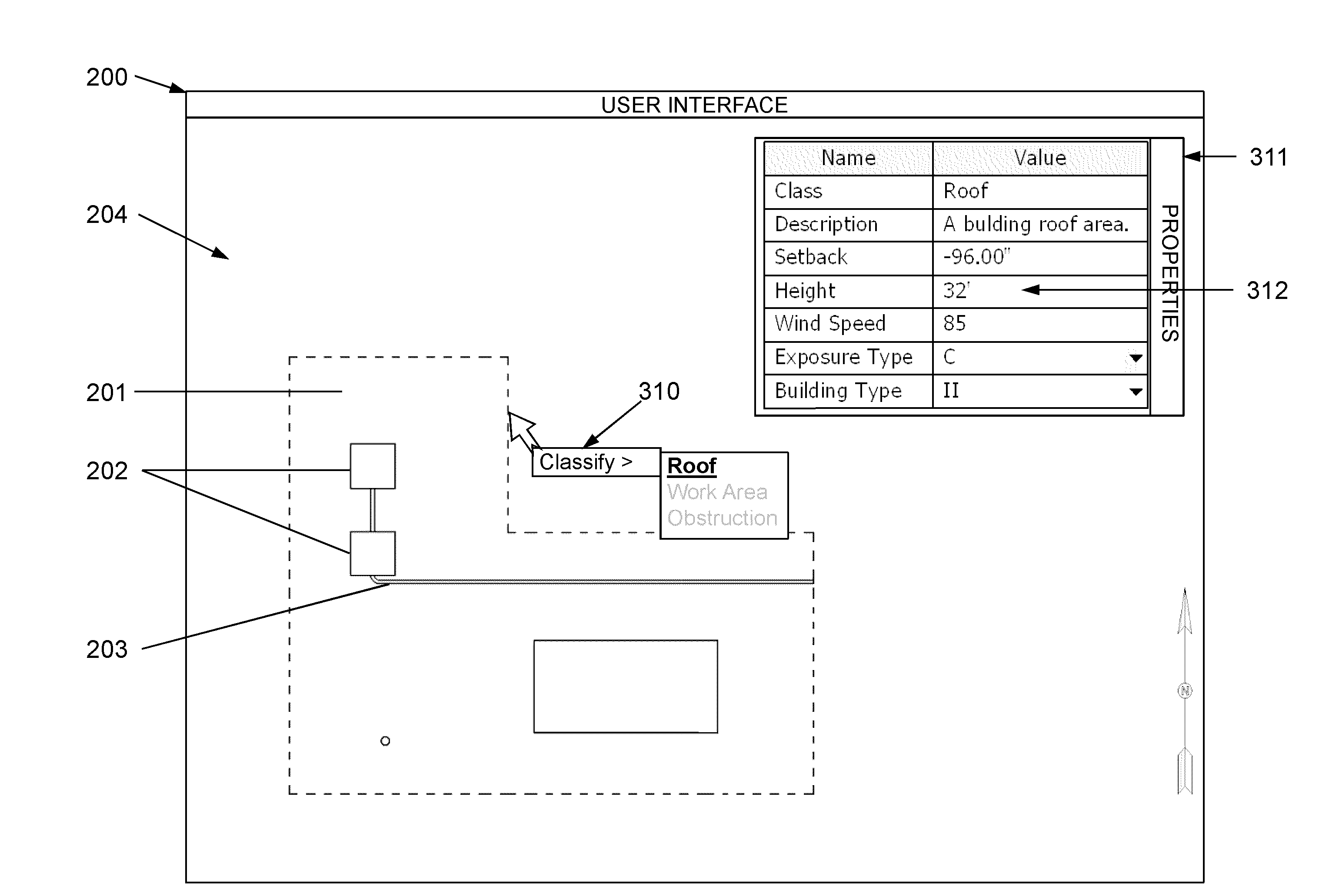
[0033]Computer aided design systems (CAD) have been in commercial use for many decades. CAD systems provide efficient methods to automate the creation, editing, presentation, and retrieval of design information. The power of CAD systems has been enhanced through the use of “knowledge-based” programming techniques whereby engineering and / or design rules can be formalized, encoded and executed to automate portions of the design process or to detect potential design errors. A common example of a knowledge-based system is the grammar checking function found in most commercial word processors whereby many rules of English grammar have been encoded and are automatically applied to text documents to highlight potential errors and suggest corrective action.

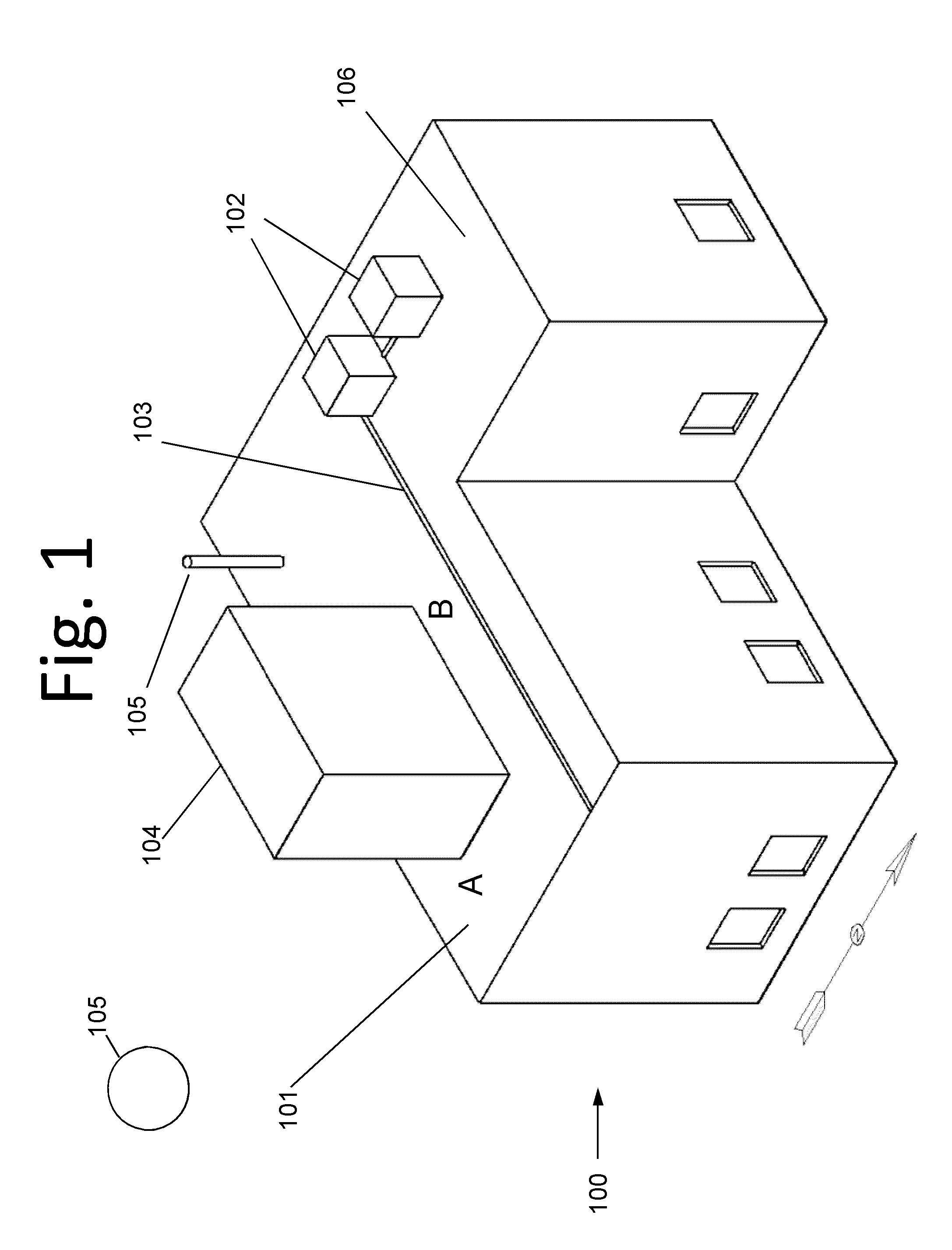
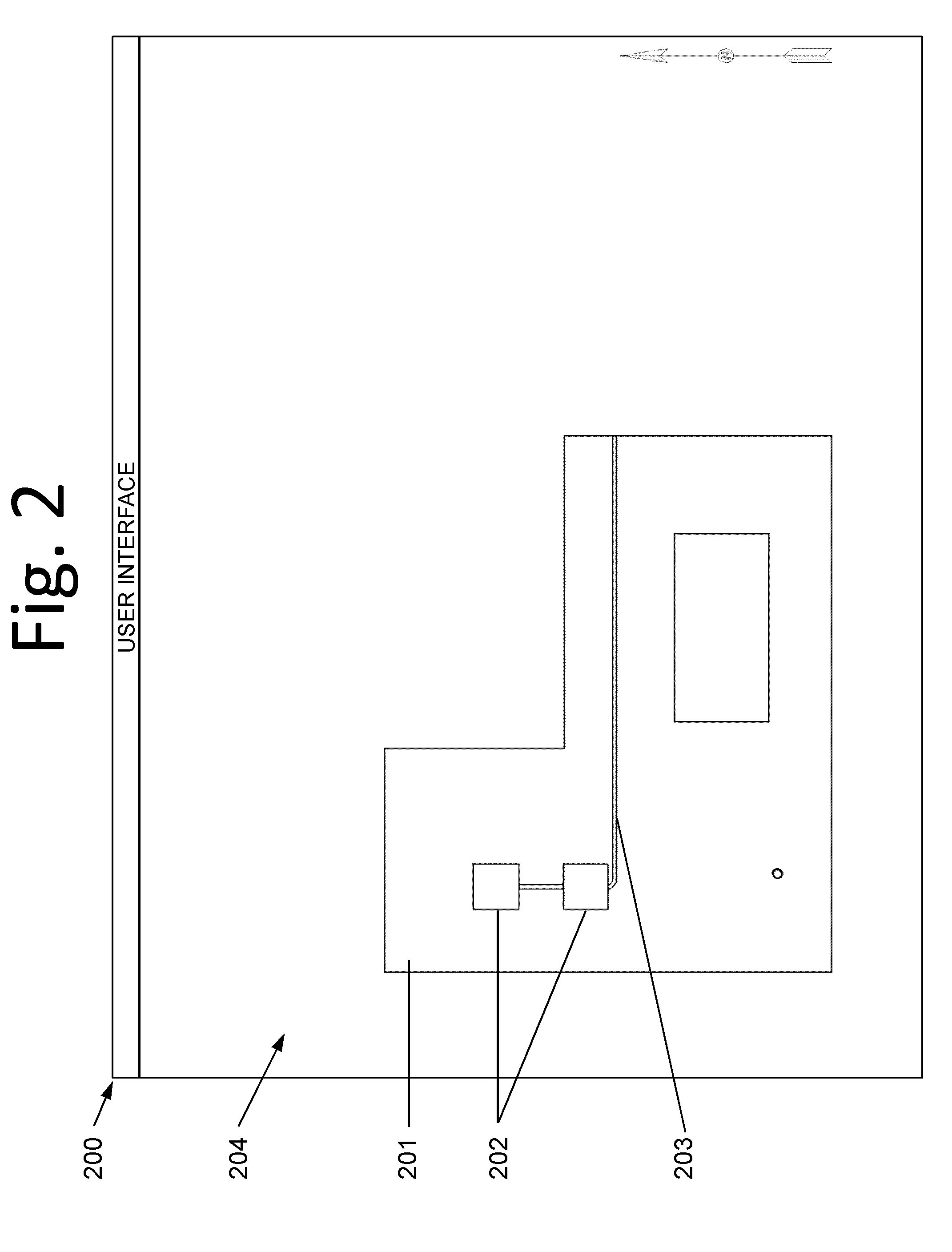
[0034]The systems and methods described herein involve the application of knowledge-based CAD techniques for the automatic layout, evaluation, and optimization of solar energy system designs consistent with a large number of design constr...


PUM


Abstract

Embodiments may include systems and methods to create and edit a representation of a worksite, to create various data objects, to classify such objects as various types of pre-defined “features” with attendant properties and layout constraints. As part of or in addition to classification, an embodiment may include systems and methods to create, associate, and edit intrinsic and extrinsic properties to these objects. A design engine may apply of design rules to the features described above to generate one or more solar collectors installation design alternatives, including generation of on-screen and/or paper representations of the physical layout or arrangement of the one or more design alternatives. Embodiments may also include definition of one or more design apertures, each of which may correspond to boundaries in which solar collector layouts should comply with distinct sets of user-defined design preferences. Distinct apertures may provide heterogeneous regions of collector layout according to the user-defined design preferences.

Description

RELATED APPLICATIONS[0001]This application claims the benefit of priority under 35 U.S.C. §119(e) of U.S. Provisional Application No. 61 / 154,347, filed on Feb. 20, 2009, and entitled “AUTOMATED SOLAR COLLECTOR INSTALLATION DESIGN INCLUDING ABILITY TO DEFINE HETEROGENEOUS DESIGN PREFERENCES”, which is hereby incorporated herein by reference in its entirety.STATEMENT OF GOVERNMENT SUPPORT[0002]The invention described herein was made with governmental support under contract number DE-FC36-07GO17043 awarded by the United States Department of Energy. The United States Government may have certain rights in the invention.BACKGROUND OF THE INVENTION[0003]In recent years, solar power has become an increasingly important source of energy. Solar energy may be collected and harnessed in numerous ways, including through the use of solar collectors such as photovoltaic (PV) modules and solar-thermal heat and power collectors and converters. The size of these projects may vary tremendously—from si...

Claims


Application Information

Patent Timeline
Patent Type & Authority Applications(United States)
IPC IPC(8): G06F17/50F24S23/00
CPCF24J2/00G06F17/50G06F17/5004F24J2200/04F24S2201/00G06F30/13G06F30/00
Inventor WAYNE, GARYFRUMKIN, ALEXANDERZAYDMAN, MICHAELLEHMAN, SCOTTBRENNER, JULES
Owner SUNPOWER CORPORATION
Why Eureka
Try Eureka