Electric-powered transfer cylinder for landing gear system

a technology of electric power transfer and landing gear, which is applied in the direction of spring/damper, shock absorber, vibration damper, etc., can solve the problems of strut shrinkage, and achieve the effect of sufficiently compact and high hydraulic fluid flow ra

Active Publication Date: 2010-09-02
THE BF GOODRICH CO
View PDF6 Cites 77 Cited by
  • Summary
  • Abstract
  • Description
  • Claims
  • Application Information

AI Technical Summary

Benefits of technology

[0006]One aspect of the invention provides a shock strut for use with aircraft landing gear that have a retract actuator, wherein the shock strut operates independently from movement of the retract actuator. The shock strut receives its power from an aircraft's hydraulic supply, but maintains a separation between the system's closed hydraulic circuit and the aircraft

Problems solved by technology

Other prior art designs provide a shrink actuator that is independent of the retract actuator but require a heavy and cumbersome mechanical linkage to exert an axial shrinking force on the strut sufficient to overcome the

Method used


Image

  • Electric-powered transfer cylinder for landing gear system
  • Electric-powered transfer cylinder for landing gear system
  • Electric-powered transfer cylinder for landing gear system

Examples


Embodiment Construction

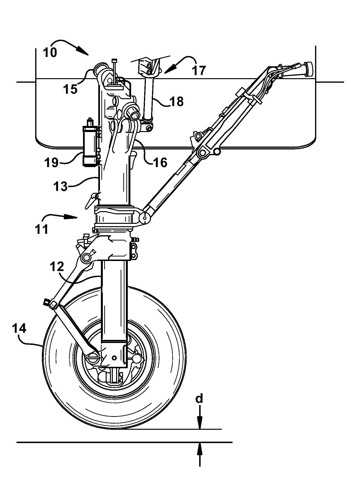
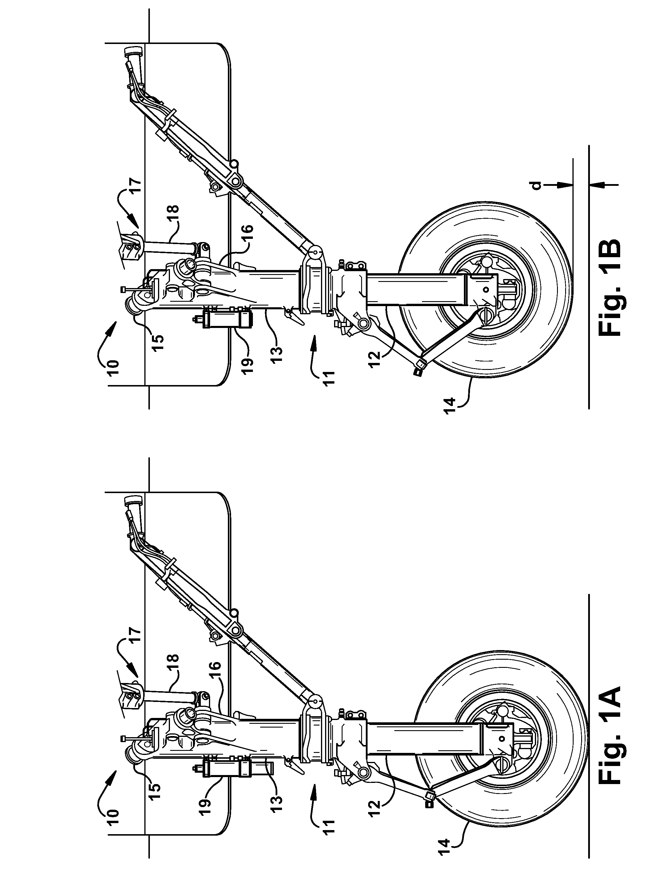
[0025]Referring now to the drawings, FIGS. 1A and 1B show an aircraft landing gear 10, depicted in a deployed and extended position in FIG. 1A, and including a strut 11 constructed in accordance with the invention. Landing gear 10 is of the type that attaches to the structure of an aircraft and is moveable between a deployed position and a retracted position. In the retracted position landing gear 10 is housed within the fuselage of the aircraft. One skilled in the art will readily understand that the invention herein disclosed can be adapted for use in conjunction with body mounted or nose mounted landing gear. In addition, the shock strut can be included in laterally retracting as well as forward and aft retracting landing gear configurations.

[0026]In FIG. 1B, the landing gear 10 is shown in a deployed but shortened or “shrunk” position. In this position, the strut 11 has been shortened by a distance “d.”

[0027]Referring now to FIGS. 1A and 1B in greater detail, landing gear 10 inc...


PUM


Abstract

A shock strut for an aircraft landing gear having a retract actuator that is moveable in length to deploy or retract the landing gear, that includes a shrink strut and a transfer device. The shrink strut may be compressed in length for stowage in the fuselage. The transfer device may be in closed fluid communication with the strut shrink for transferring and receiving hydraulic fluid to and from the strut shrink. When actuated by an aircraft hydraulic or electric system independent of any motion of the retract actuator, the transfer device may drive hydraulic fluid to the strut shrink thereby compressing or shrinking the shrink strut to a partially compressed length.

Description

PRIORITY CLAIM[0001]This application claim priority to and is a continuation-in-part of commonly-owned U.S. patent application Ser. No. 12 / 256,204 filed on Oct. 22, 2008, which is hereby incorporated by reference in its entirety.FIELD OF INVENTION[0002]This invention relates generally to actuation devices used to shrink a shock strut of an aircraft landing gear, and more specifically relates to an electric-powered transfer cylinder in fluid communication with the shock strut.BACKGROUND OF THE INVENTION[0003]In the design and manufacture of aircraft, it is generally desirable to minimize the space required by aircraft components. One approach to saving space is to shorten the length of the landing gear before or during retraction into a stowed position in the aircraft. The shortened length of the landing gear may be required by the initial design of an aircraft or may be desired to minimize design changes in future generations of an existing aircraft.[0004]A prior art design for shor...

Claims


Application Information

Patent Timeline
IPC IPC(8): B64C25/10
CPCB64C25/14B64C25/22F16F9/065B64C25/60B64C2025/008B64C25/24
Inventor LUCE, WILLIAM E.
Owner THE BF GOODRICH CO
Why Eureka
Try Eureka