Vibration isolator

a technology of vibration isolators and isolators, which is applied in the direction of shock absorbers, machine supports, mechanical equipment, etc., can solve the problems of increasing the number of components and the assembly of the vibration isolator to vehicles or the like is much troublesome, so as to simplify the pipeline structure and simplify the connection work

Inactive Publication Date: 2010-09-02
PROSPIRA CORP
View PDF4 Cites 6 Cited by
  • Summary
  • Abstract
  • Description
  • Claims
  • Application Information

AI Technical Summary

Benefits of technology

[0018]It will be appreciated from the foregoing description that, with the vibration isolator according to the present invention, it is possible to simplify the pipeline structure for connecting the operating pressure supply source to the negative pressure chamber with the membrane as a partition wall, and also to the valve chamber of the valve mechanism for opening or closing the second restricted passage, and to simplify the connection work for connecting the negative pressure chamber and the valve chamber to the operating pressure supply source.
[0019]The present invention will be described below with reference to a preferred embodiment shown in the accompanying drawings, wherein:
[0020]FIG. 1 is a longitudinal-sectional view showing an embodiment of the vibration isolator according to the present invention in a shaking mode;
[0021]FIG. 2 is a longitudinal-sectional view showing the vibration isolator of FIG. 1 in an idling mode; and
[0022]FIGS. 3(A) and 3(B) are, respectively, a longitudinal-sectional view and a perspective view, showing the structure of the partition member in the vibration isolator of FIG. 1.
[0048]130 . . . intake manifold (operating pressure supply passage)

Problems solved by technology

Therefore, in the vibration isolator according to Patent Document 1, due to the requirement for the provision of two independent internal passage systems within the vibration isolator and for the provision of two air pipelines on the outside of the vibration isolator, for connecting the two internal passage systems, respectively, to the operating pressure supply sources, not only the number of components of the vibration isolator increases, but also the assembly of the vibration isolator to vehicles or the like is much troublesome in that the two air pipelines must be connected to the two internal passage systems while preserving sealing function at the connections.

Method used


Image

  • Vibration isolator
  • Vibration isolator
  • Vibration isolator

Examples


Embodiment Construction

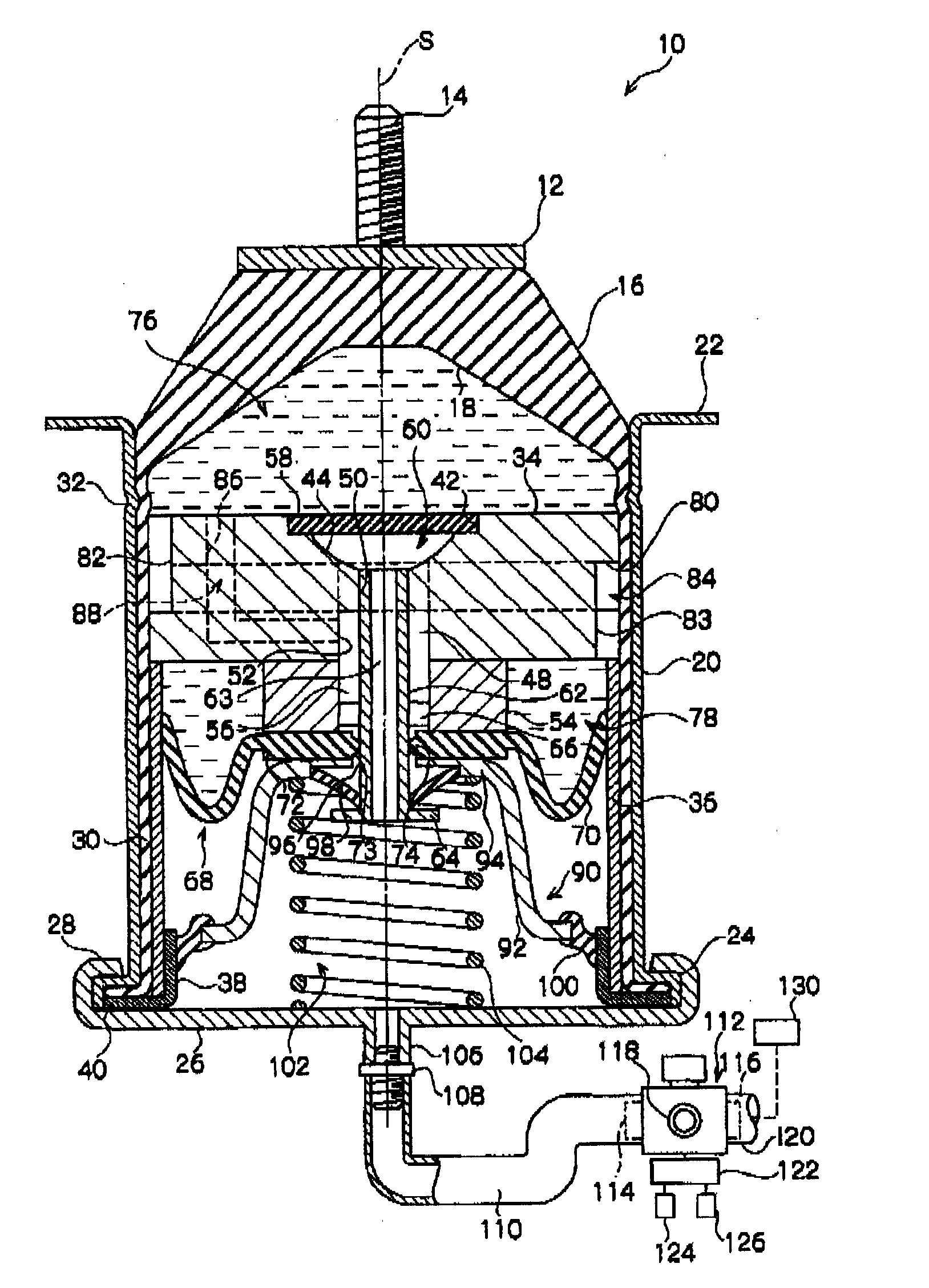
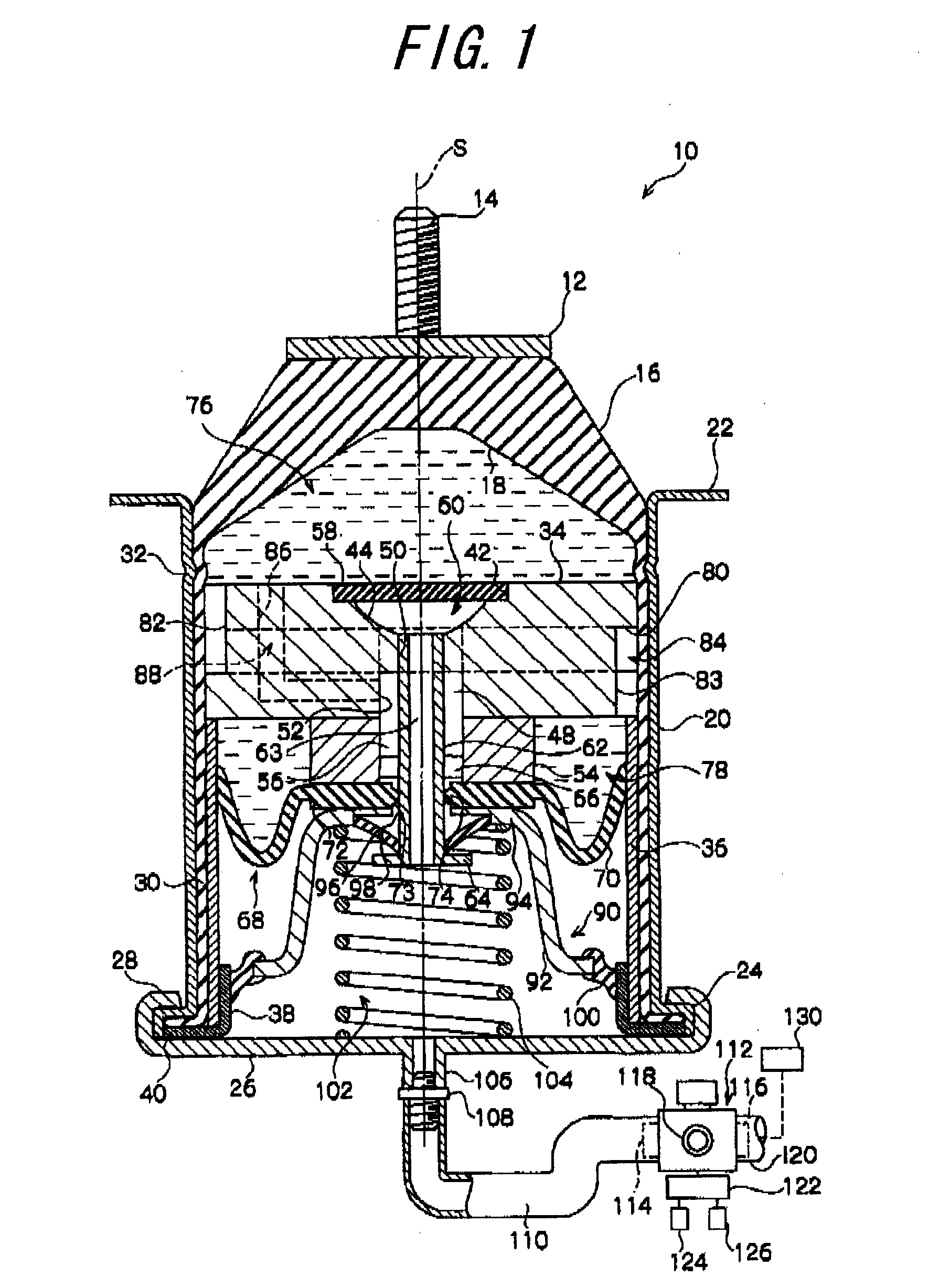
[0049]FIG. 1 shows an embodiment of the vibration isolator according to the present invention. The vibration isolator 10 is applicable to an engine mount for mounting an engine of automobile or the like vehicle, as a vibration source, on a vehicle body as a vibration reception portion. A vertical imaginary line identified by symbol S denotes a center axis of the vibration isolator. The direction along the center axis S is defined as the axial direction of the vibration isolator.

[0050]As shown in FIG. 1, the vibration isolator 10 is provided on its top end with a thick disc-like fitting 12 and comprises a thin cylindrical outer cylinder member 20 that is arranged on the lower side of the fitting 12 coaxially thereto. A threaded shaft 14 projects along the center axis S from the center portion of the upper surface of the fitting 12, and is fixedly secured to the fitting 12 by welding or the like. The fitting 12 is fixedly secured to the engine side through the threaded shaft 14. The o...


PUM


Abstract

A vibration isolator (10) enabling simplification of a passage structure for connecting a negative pressure chamber in which a membrane is used as a partition wall and a valve chamber of a valve mechanism for opening and closing a second restriction passage to an operating pressure supply source, and simplification of connection of the negative pressure chamber and the valve chamber of the valve mechanism to the operating pressure supply source. The inner passage (63) of a communication tube (62) on the inner peripheral side of an outer cylinder member (20) communicates the negative pressure chamber (60) with the valve chamber (102). A pipe connection part (106) and a supply/discharge pipe (110) communicate the valve chamber (102) with the supply/discharge port (114) of a switching valve (112) on the outside of the vibration isolator (10). The switching valve (112) selectively communicates the supply/discharge port (114) to either an intake manifold (130) as the negative pressure supply source, or an atmosphere space. The negative pressure chamber (60) communicates with the valve chamber (102) through the communication tube (62) on the inner peripheral side of the outer cylinder member (20). Thus, either of a negative pressure and an atmospheric pressure, which is same as a pressure in the valve chamber (102), can be supplied into the negative pressure chamber (60), by supplying either of the negative pressure and the atmospheric pressure into the valve chamber (102) through the supply/discharge pipe (110) and the pipe connection part (106).

Description

TECHNICAL FIELD[0001]The present invention relates to a vibration isolator, which is applied to automobiles, general industrial machineries and the like, for isolating and absorbing vibration transmitted from a vibration source, such as an engine, to a vibration reception portion, such as a vehicle body.BACKGROUND ART[0002]In automobiles, vibration isolators are arranged between an engine and a vehicle body (or frame). One example of vibration isolator applied as an engine mount is disclosed in Patent Document 1: Japanese Patent Application Laid-open Publication No. 2005-23974, which is in the form of a liquid-type isolator. The vibration isolator disclosed in Patent Document 1 includes a liquid space liquid-tightly sealed from outside by an outer cylinder, an elastic body formed of rubber, and a diaphragm. The liquid space is divided by a partition member into a main liquid chamber with the elastic member forming part of its walls, and an auxiliary liquid chamber with the diaphragm...

Claims


Application Information

Patent Timeline
Patent Type & Authority Applications(United States)
IPC IPC(8): F16F13/08F16F13/26
CPCF16F13/268F16F13/264
Inventor KOJIMA, HIROSHI
Owner PROSPIRA CORP
Why Eureka
Try Eureka