Multiple-Stage Charge Pump with Charge Recycle Circuit

a charge pump and recycle circuit technology, applied in the field of multi-stage charge pumps, can solve the problems of high power consumption of conventional multiple-stage charge pump circuits, and achieve the effect of low power consumption and higher power efficiency

Inactive Publication Date: 2010-09-02
MACRONIX INT CO LTD
View PDF9 Cites 13 Cited by
  • Summary
  • Abstract
  • Description
  • Claims
  • Application Information

AI Technical Summary

Benefits of technology

[0008]The invention is directed to a multiple-stage charge pump circuit with lower power consumption and higher power efficiency in comparison to the conventional multiple-stage charge pump circuit.

Problems solved by technology

However, the conventional multiple-stage charge pump circuit has the disadvantages of high power consumption because the capacitor C is repeatedly charged and discharged.

Method used


Image

  • Multiple-Stage Charge Pump with Charge Recycle Circuit
  • Multiple-Stage Charge Pump with Charge Recycle Circuit
  • Multiple-Stage Charge Pump with Charge Recycle Circuit

Examples


Embodiment Construction

[0017]The present invention provides a multiple-stage charge pump circuit which uses a charge recycle circuit for transferring charge stored in a charge pump stage circuit to another charge pump stage circuit through a short circuit path formed by the charge recycle circuit, so as to reuse the charge.

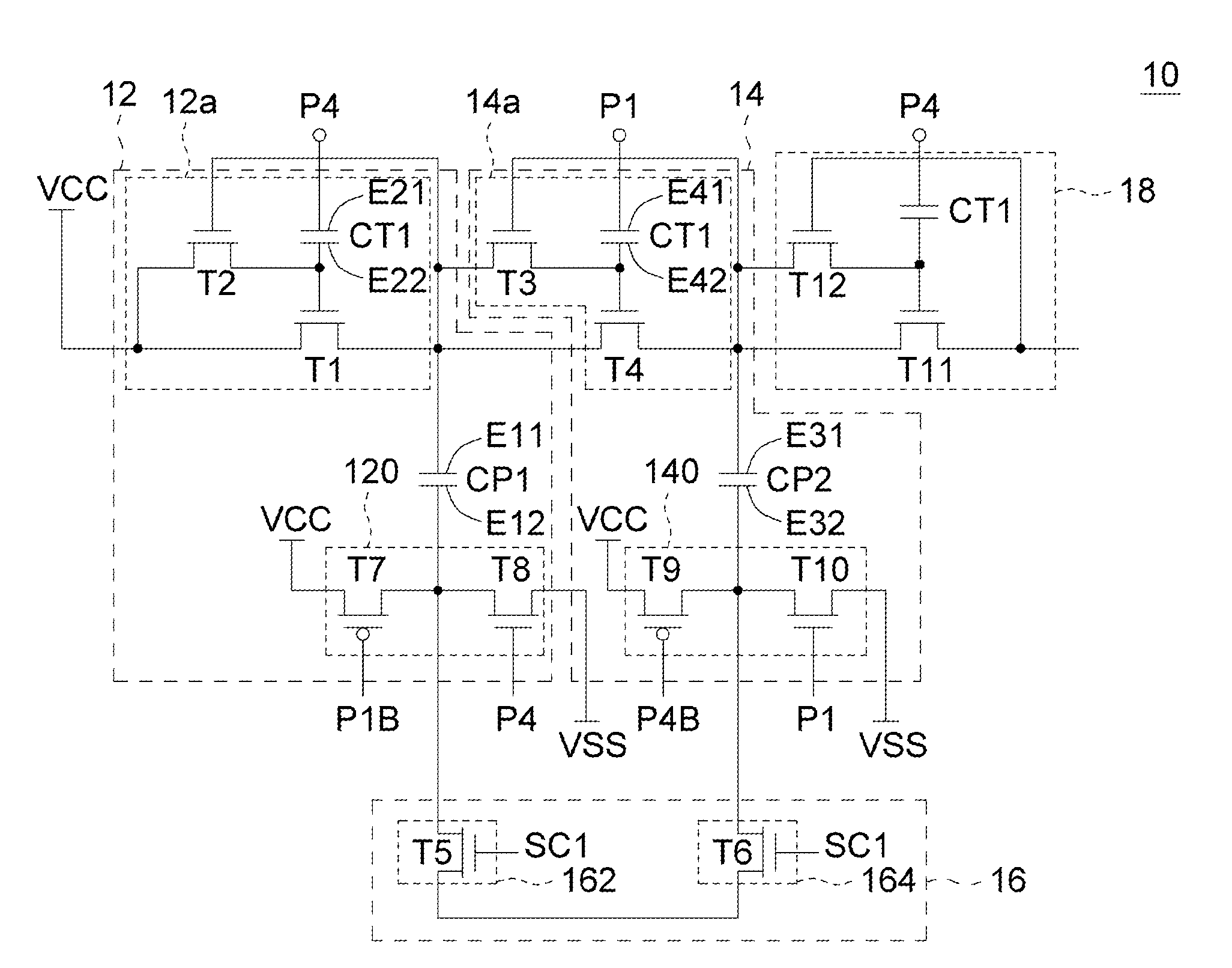
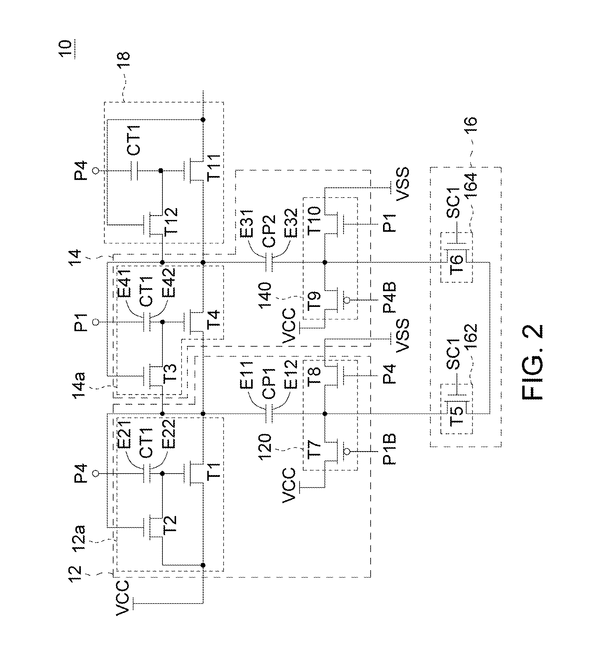
[0018]Referring to FIG. 2 and FIG. 3, a circuit diagram of the multiple-stage charge pump circuit of the embodiment and a waveform diagram of the signals in FIG. 2 are respectively shown. The multiple-stage charge pump circuit 10 comprises stage circuits 12, 14, and a charge recycle circuit 16. The first stage circuit 12 includes a transfer circuit 12a, a pump capacitor CP1, and a voltage driving circuit 120. The transfer circuit 12a includes a transfer capacitor CT1 and transistors T1, T2.

[0019]The pump capacitor CP1 has first end E11 and second end E12. The transfer capacitor CT1 has first end E21 and second end E22. The first and the second transistors T1 and T2 are, for example, N-t...


PUM


Abstract

A multiple-stage charge pump circuit comprises first and second pump capacitors, first and second transfer circuits, first and second driving circuits, and a charge recycle circuit. The first pump capacitor, the first transfer circuit, and the first driving circuit form a first stage circuit, and the second pump capacitor, the second transfer circuit and the second driving circuit form a second stage circuit. The first and the second stage circuits operate 180 degree out of phase with each other. The charge recycle circuit transfers the charge at the second end of the first pump capacitor to the second end of the second pump capacitor in a first time interval, and transferring the charge at the second end of the second pump capacitor to the second end of the first pump capacitor in a second time interval.

Description

[0001]This application is a continuation-in-part (CIP) application of the co-pending application Ser. No. 11 / 938,314, filed on Nov. 12, 2007.BACKGROUND OF THE INVENTION[0002]1. Field of the Invention[0003]The invention relates in general to a multiple-stage charge pump, and more particularly to a multiple-stage charge pump with a charge recycle circuit.[0004]2. Description of the Related Art[0005]With the increasing development of technology, multiple-stage charge pump has been widely used in the circumstances for providing voltage exceeding the voltage of the circuit power supply, for example, to write and erase operation in EEPROM.[0006]Referring to FIG. 1, a circuit diagram of a conventional multiple-stage charge pump is shown. The conventional multiple-stage charge pump 100 includes four stages 120 and each of the stages 120 includes a diode D and a pump capacitor C. Clock signals CK1 and CK2 are 180 degree out of phase with each other for respectively turning on the diodes of t...

Claims


Application Information

Patent Timeline
Patent Type & Authority Applications(United States)
IPC IPC(8): G05F3/02
CPCH02M3/073
Inventor CHEN, CHUNG-KUANGHUNG, CHUN-HSIUNGSHIH, YI-TE
Owner MACRONIX INT CO LTD
Why Eureka
Try Eureka