
Permanent-magnet magnetic field generator

Inactive Publication Date: 2010-09-02
SHIN ETSU CHEM IND CO LTD
View PDF20 Cites 13 Cited by
  • Summary
  • Abstract
  • Description
  • Claims
  • Application Information

AI Technical Summary

Benefits of technology

[0010]The present invention makes it possible to easily fabricate a variable-magnetic-field dipole-ring magnetic field generator, and also to increase the size of the device for industrial use because the device is capable of stable driving without displacement due to vibration thereof.

Problems solved by technology

Due to the characteristics of the magnetic field generator, the skew angle is substantially 0° near the central axis of the ring of the device, but tends to become worse, i.e., increase as the point becomes closer to the inner wall of the magnetic field generator.

Method used


Image

  • Permanent-magnet magnetic field generator
  • Permanent-magnet magnetic field generator
  • Permanent-magnet magnetic field generator

Examples


example 1

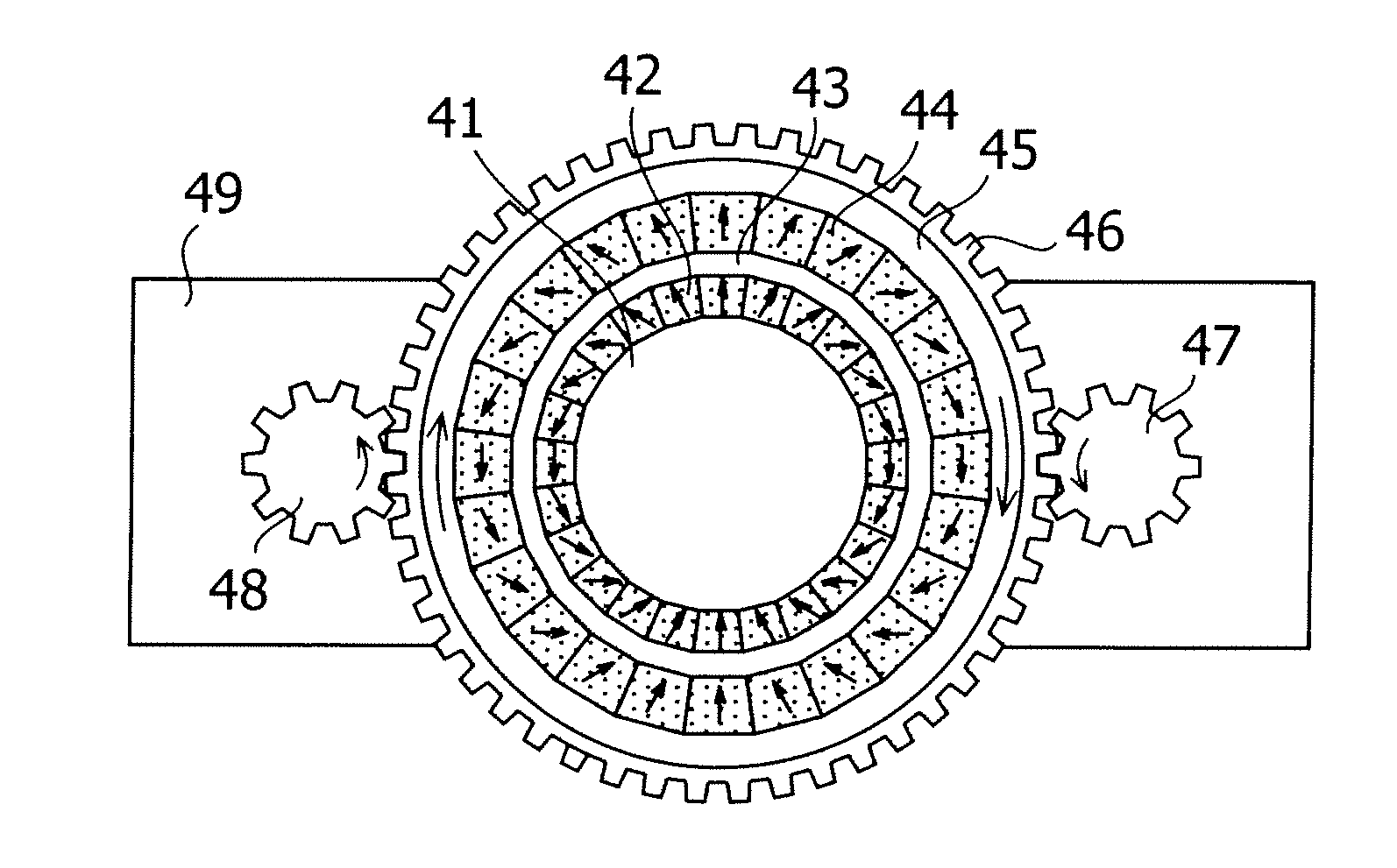
[0058]A dipole-ring magnetic field generator having the same structure as that of the generator shown in FIG. 5 was fabricated. The dipole-ring magnetic field generator comprised an inner dipole ring (inner diameter: 60 mm, outer diameter: 145 mm, height: 200 mm) and an outer dipole ring (inner diameter: 155 mm, outer diameter: 230 mm, height: 200 mm), and the magnetization direction of each permanent magnet (neodymium rare earth magnet) of the rings was same as those shown in FIG. 6. A ring being made of polyacetal resin and having a thickness of 5 mm was used as a friction-resistant ring. A spur gear (commercial product) made of carbon steel was used as a small gear of a driving transmission mechanism. A gear of the same type as the small gear was used as a counter gear and connected not to a motor but to the outer dipole ring.

[0059]The magnets of the outer dipole ring were rotated (at 2 rpm) with the magnets of the inner dipole ring fixed, and a magnetic field generated at the in...


PUM


Abstract

A high-performance variable-magnetic-field dipole-ring magnetic circuit is provided. Specifically, provided is a permanent-magnet magnetic field generator having inner and outer dipole rings which share a central axis, and a yoke which surrounds the dipole rings, wherein a unidirectional variable magnetic field is generated in a space within the inner dipole ring. The generator has a fastener for fixing the inner dipole ring, and a rotator for allowing the outer dipole ring to rotate around the central axis. In the generator, each of the inner and outer dipole rings has a plurality of permanent magnets arranged in such a ring shape that a magnetization direction of the permanent magnets can make a full rotation per half circle of the ring.

Description

BACKGROUND OF THE INVENTION[0001]1. Field of the Invention[0002]The present invention relates to a permanent-magnet magnetic field generator.[0003]2. Description of the Related Art[0004]A dipole-ring magnetic circuit comprises a plurality of magnet elements arranged in such a ring shape that the magnetization direction of the magnet elements can make a full rotation per half circle of the ring. The dipole-ring magnetic circuit is configured to generate a substantially unidirectional magnetic field in an internal space within the ring. Such a dipole-ring magnetic circuit is widely used, for example, for a magnetic resonance imaging (MRI) apparatus, a semiconductor device fabrication process, and a uniform magnetic field generator for fundamental research. Conventionally, normal electromagnets, superconducting electromagnets, or the like are used as a generator for generating a uniaxial uniform magnetic field. However, as a result of the recent development of high-performance rare ear...

Claims


Application Information

Patent Timeline
IPC IPC(8): H01F7/02
CPCH01F7/0284G01R33/383
Inventor HIGUCHI, DAI
Owner SHIN ETSU CHEM IND CO LTD
Learn More