Display apparatus and fabrication method for display apparatus

a technology for display apparatus and fabrication method, applied in the field of display apparatus, can solve the problems of increasing the number of fabrication steps, increasing the number of kinds of materials, and giving rise to the increase of fabrication cost, and achieves the effect of simple configuration and high degree of accuracy

Active Publication Date: 2010-09-02
JAPAN DISPLAY WEST
View PDF3 Cites 34 Cited by
  • Summary
  • Abstract
  • Description
  • Claims
  • Application Information

AI Technical Summary

Benefits of technology

[0015]According to the present invention, light of a predetermined wavelength can be detected wit

Problems solved by technology

Since the technique of Japanese Patent Laid-Open No. 2005-275644 includes an IR filter, it gives rise to increase of the number

Method used


Image

  • Display apparatus and fabrication method for display apparatus
  • Display apparatus and fabrication method for display apparatus
  • Display apparatus and fabrication method for display apparatus

Examples


first embodiment

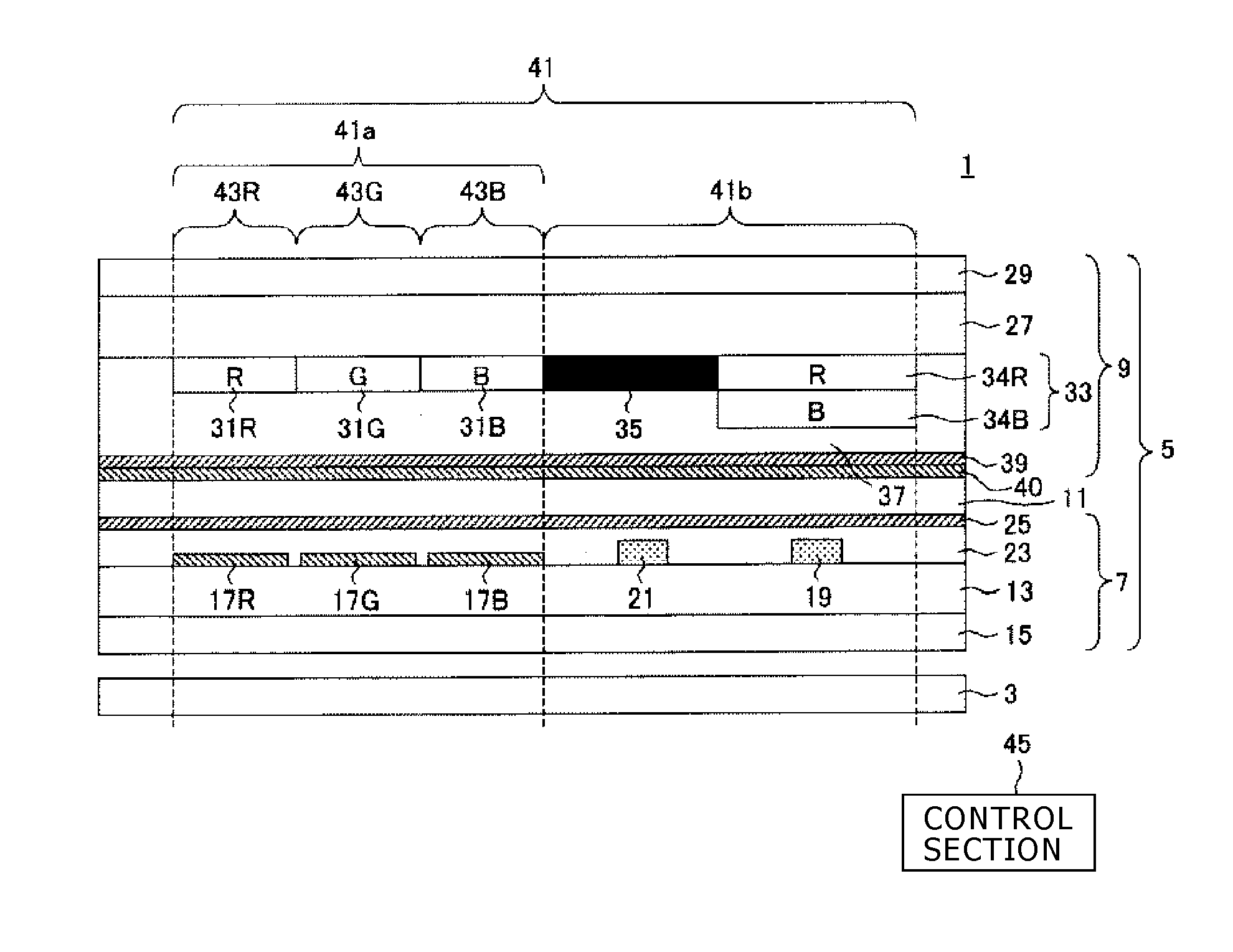
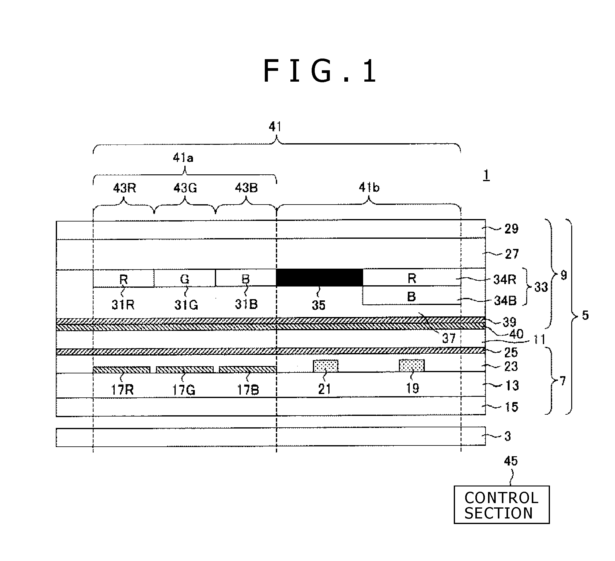
[0029]FIG. 1 is a sectional view schematically showing a general configuration of a liquid crystal display apparatus 1 according to a first embodiment of the present invention.

[0030]In the liquid crystal display apparatus 1, a plurality of pixels 41 are arrayed in rows and columns as viewed in plan (as viewed from above the plane of FIG. 1). It is to be noted that, in FIG. 1, a sectional view of a pixel 41 among the plurality of pixels 41 is shown. For the plural pixels 41, a display region 41a for displaying an image on a screen 55a (refer to FIG. 4) and a detection region 41b for detecting light incident from the screen 55a are provided. In the display region 41a, a plurality of subpixels 43R, 43G and 43B are provided corresponding to a plurality of colors (wavelength regions of a plurality of kinds of light). The subpixels 43R, 43G and 43B correspond, for example, to red (R), green (G) and blue (B).

[0031]It is to be noted that, in the following description, R, G and B are added t...

second embodiment

[0073]FIG. 5 is a sectional view schematically showing a general configuration of a liquid crystal display apparatus 101 of a second embodiment.

[0074]The liquid crystal display apparatus 101 of the second embodiment is different in the configuration of an IR filter 133 in comparison with the liquid crystal display apparatus 1 of the first embodiment. In particular, while the IR filter 33 in the first embodiment is formed from the two kinds of filter composition layers 34R and 34B, the IR filter 133 in the second embodiment is formed from filter composition layers 34R, 34G and 34B corresponding to all types (three colors) of the color filters 31.

[0075]It is to be noted that, since the thickness of the filter composition layers 34 is equal to the thickness of the color filters 31, the thickness of the IR filter 133 in the second embodiment is 3 / 2 times the thickness of the IR filter 33 in the first embodiment, and a CF substrate 109 and a display panel 105 are thicker then the CF subs...


PUM


Abstract

A display apparatus is provided which can detect light of a predetermined wavelength with a high degree of accuracy from within light incident from a screen by a simple configuration. The display apparatus includes a CF substrate (9) having a plurality of color filters (31) of different colors for passing light for displaying an image on the screen (55a) and an IR filter (33) provided in a region different from an arrangement region of the color filters of the different colors for passing light incident from the screen (55a), and a main sensor (19) provided on the rear side of the IR filter (33) for detecting light incident from the screen (55a) and passing through the IR filter (33). The IR filter (33) has a laminate of filter materials same as filter materials from which at least two or more ones of the color filters of the different colors are formed respectively.

Description

TECHNICAL FIELD[0001]This invention relates to a display apparatus capable of detecting light incident from a screen and a fabrication method for the display apparatus.BACKGROUND ART[0002]A display apparatus is known which selectively detects light of a particular wavelength from within light incident thereto. For example, a liquid crystal display apparatus of Japanese Patent Laid-Open No. 2005-275644 is a display apparatus of the so-called touch sensor type and detects infrared rays emitted from a backlight and reflected by a detection object such as a finger of a user positioned in the proximity of a screen by means of a plurality of optical sensors disposed for individual pixels to detect proximity and contact of the detection object to and with the screen. While light of various wavelengths is included in light incident from the screen, since the transmission factor of infrared rays through a liquid crystal panel is higher than that of visible rays, only the infrared rays can be...

Claims


Application Information

Patent Timeline
IPC IPC(8): G02F1/1335G03F7/20
CPCG02F1/13338G02F1/133514G02F2001/13312G06F3/0421G02F2203/11G06F3/0412G02F2201/52G02F1/13312G02F1/1335
Inventor TAKAMA, DAISUKETATEUCHI, MITSURUHARADA, TSUTOMU
Owner JAPAN DISPLAY WEST
Why Eureka
Try Eureka