Method and device for measuring a mean value of visco-elasticity of a region of interest

a technology of viscoelasticity and measuring device, which is applied in the direction of ultrasonic/sonic/infrasonic diagnostics, instruments, applications, etc., can solve the problems of time and processing, large amount of tissue energy deposit, and not being implemented in real time on medical imaging devices. , to achieve the effect of reducing the quantity of tissue energy induced, avoiding tissue degradation, and increasing the time separation

Active Publication Date: 2010-09-02
SUPER SONIC IMAGINE
View PDF18 Cites 39 Cited by
  • Summary
  • Abstract
  • Description
  • Claims
  • Application Information

AI Technical Summary

Benefits of technology

[0060]This enables to limit the quantity of energy induced in the tissue in order to avoid tissue degradations. It is particularly important for biological tis

Problems solved by technology

Usually those imaging techniques are time and processing consuming.
Most of the time, they require huge amount of energy deposit in the tissue.
For those reasons they have not being implemented to date in real time on a medical imaging device.
However such technique s

Method used


Image

  • Method and device for measuring a mean value of visco-elasticity of a region of interest
  • Method and device for measuring a mean value of visco-elasticity of a region of interest

Examples


first embodiment

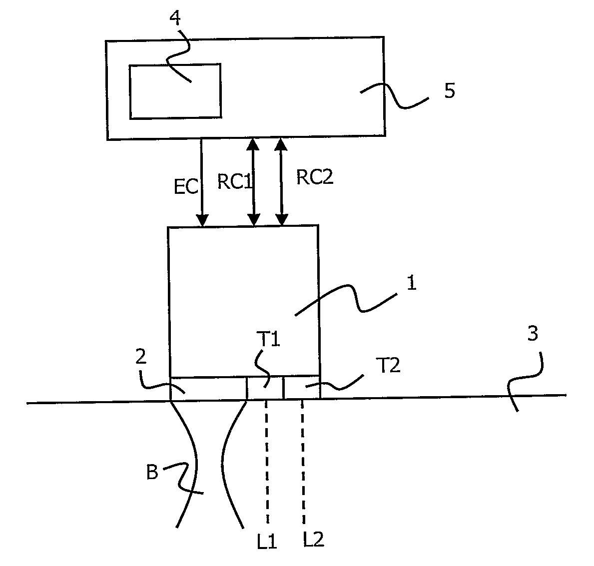
[0083]FIG. 1 shows a device 1 in accordance with the invention. It consists in a so called “1D” probe including three transducers 2, T1 and T2.

[0084]First transducer 2 is dedicated to generate a shear wave in tissue 3.

[0085]It can be qualified as “pushing” transducer and works, for example at a central frequency of 3 MHz.

[0086]In such a case, it is designed to generate an ultrasound beam B, said beam B being advantageously of a few mm width and in a depth range between 2 and 6 cm.

[0087]Said ultrasound beam B can be of such a power that it can create a shear wave SW in the tissue 3.

[0088]The two other transducers T1 and T2 are imaging transducers dedicated to image the tissue 3 along two ultrasound lines L1 and L2. Said transducers T1 and T2 advantageously emit ultrasounds of central frequency 5 MHz. They are advantageously separated by 1-2 cm. Simultaneous or time-shifted emissions may be implemented.

[0089]Both ultrasound lines L1 and L2 are positioned in the vicinity of a region of...

second embodiment

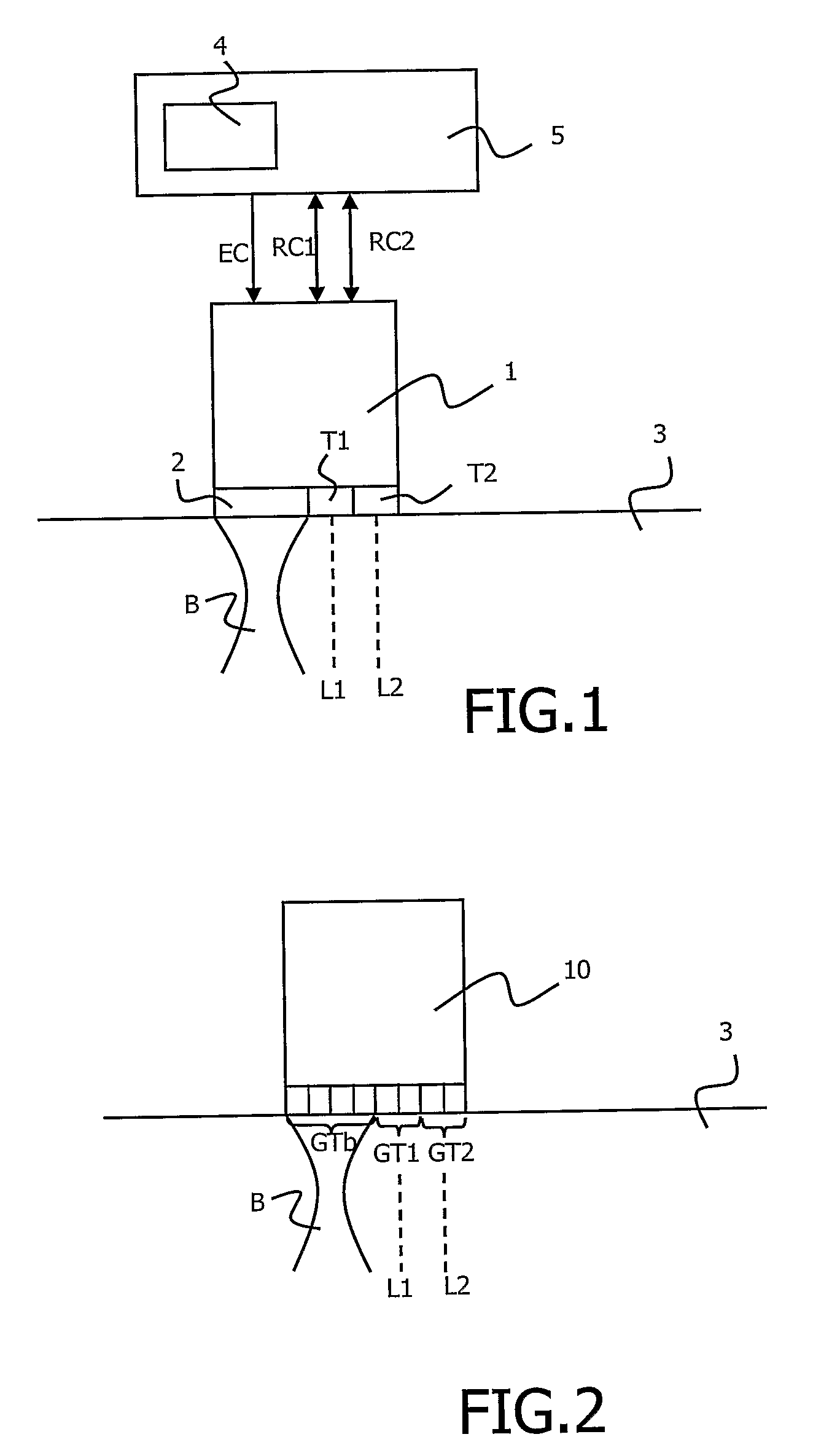
[0104]FIG. 2 shows a measurement device in accordance with the present invention. It consists in an implementation of the method in an echographic imaging system using an ultrasound array probe 10 to image the tissue 3.

[0105]The following describes how a real time echographic system with mean visco-elasticity measurement and display is thus obtained.

[0106]Said echographic system is advantageously controlled in order to generate an ultrasound pushing beam B in the tissue 3.

[0107]As illustrated on FIG. 2, such beam B may be obtained by specific focusing of ultrasound emitted by a group GTb of transducers located on one of the sides of the transducer array 10.

[0108]Two other transducers or group of transducers GT1, GT2 are subsequently used to image two lines of interest L1 and L2.

[0109]Advantageously, first, a classical ultrasound imaging sequence is performed to compute an ultrasound image of the region of interest. This is an approximately 20 ms long step.

[0110]Then the global elast...


PUM


Abstract

The invention relates to a method for measuring a mean visco-elasticity value for a soft material. Said method using a single probe carrying at least one transducer comprises the steps of:
    • a) inducing, in a constraint zone, at least one burst of mechanical vibrations in order to generate internal shear waves in the tissue propagating from said constraint zone into the tissue,
    • b1) measuring, with said transducer, the transient tissue displacements in at least one first measurement zone in the tissue, said first measurement zone being located away from said constraint zone,
    • c) estimating a mean visco-elasticity of the region of the tissue situated between the constraint zone and the first measurement zone from said measured transient tissue displacements of the tissue in the first measurement zone.

Description

FIELD OF THE INVENTION[0001]The present invention relates to a method for measuring soft tissue mechanical properties.[0002]The invention applies particularly to measuring a mean elasticity value for a soft material, like a biological tissue.BACKGROUND OF THE INVENTION[0003]Elastography techniques are devoted to measure biological tissues mechanical properties, as for example elasticity, in order to help medical diagnosis.[0004]Usually, they are implemented in medical imaging systems as additional feature of an existing imaging modality such as MRI or ultrasound.[0005]In this context, elastography gives new clinical information to the physician to help him in establishing a diagnosis.[0006]Several elastography techniques have been developed. Some are currently in clinical evaluation and some are already embedded in a medical imaging product.[0007]Schematically, elastography techniques can be divided into three different types: static, monochromatic or transient based techniques, dep...

Claims


Application Information

Patent Timeline
IPC IPC(8): A61B8/00
CPCA61B5/0048A61B8/08A61B8/485A61B8/4483G01S7/52042G01S15/8927G01S7/52036A61B5/0051G06T7/0012G01N29/44G01N29/34G01N29/36
Inventor BERCOFF, JEREMYSAVERY, DAVIDTANTER, MICKAELGENNISSON, JEAN-LUCFINK, MATHIASCOHEN-BACRIE, CLAUDE
Owner SUPER SONIC IMAGINE
Why Eureka
Try Eureka