Spot facing trochlear groove

a trochlear groove and trochlear groove technology, applied in the field of trochlear groove preparation, can solve the problems of no true anatomically based means of restoring the trochlear groove of the patient's femur, no control of the shape and depth of the resection made by these tools, and severe anterior knee pain

Active Publication Date: 2010-09-02
STRYKER CORP
View PDF47 Cites 16 Cited by
  • Summary
  • Abstract
  • Description
  • Claims
  • Application Information

AI Technical Summary

Benefits of technology

[0008]In an embodiment of this first aspect of the present invention, the guide is part of a system used to accurately restore the trochlear groove of a patient's femur with the aid of at least one reference member. A first reference member may be a flexible sizing membrane attached to a bone contacting surface of the guide. The flexible sizing membrane is a generally thin and pliable member having a perimeter that substantially matches or is rather identical to the perimeter of a prosthesis that will be implanted on the resected bone of the femur. Preferably, the bone contacting surface of the guide tracks the trochlear groove of the patient's femur. The combination of the bone contacting surface of the guide and flexible sizing membrane preferably act as visual and tactile references for locating an optimal position of the guide before any bone resection occurs.

Problems solved by technology

Patello-femoral joint disease is a condition in which the articular cartilage of the patella and / or the femoral trochlear groove is eroded due to osteoarthritis resulting in some cases in severe anterior knee pain.
However, there is very little control of the shape and depth of the resection made by these tools.
Perhaps the biggest drawback of the instruments mentioned above is that each provides no true anatomically based means of restoring the trochlear groove or patella track to ensure proper patello-femoral kinematics.
There is no systematic approach to ensure that the bone being resected will be replaced with a prosthesis that will be implanted on the resected bone.

Method used


Image

  • Spot facing trochlear groove
  • Spot facing trochlear groove
  • Spot facing trochlear groove

Examples


Embodiment Construction

[0032]As used herein, when referring to bones or other parts of the body, the term “proximal” means closer to the heart and the term “distal” means more distant from the heart. The term “inferior” means toward the feet and the term “superior” means towards the head. The term “anterior” means towards the front part of the body or the face and the term “posterior” means towards the back of the body. The term “medial” means toward the midline of the body and the term “lateral” means away from the midline of the body.

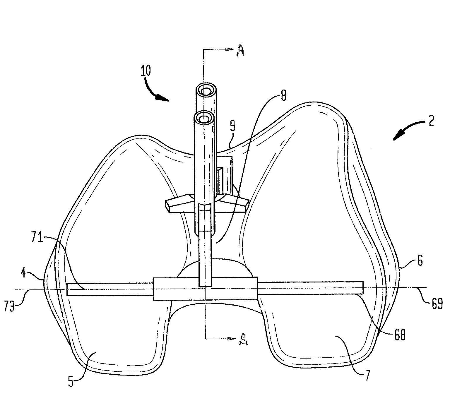
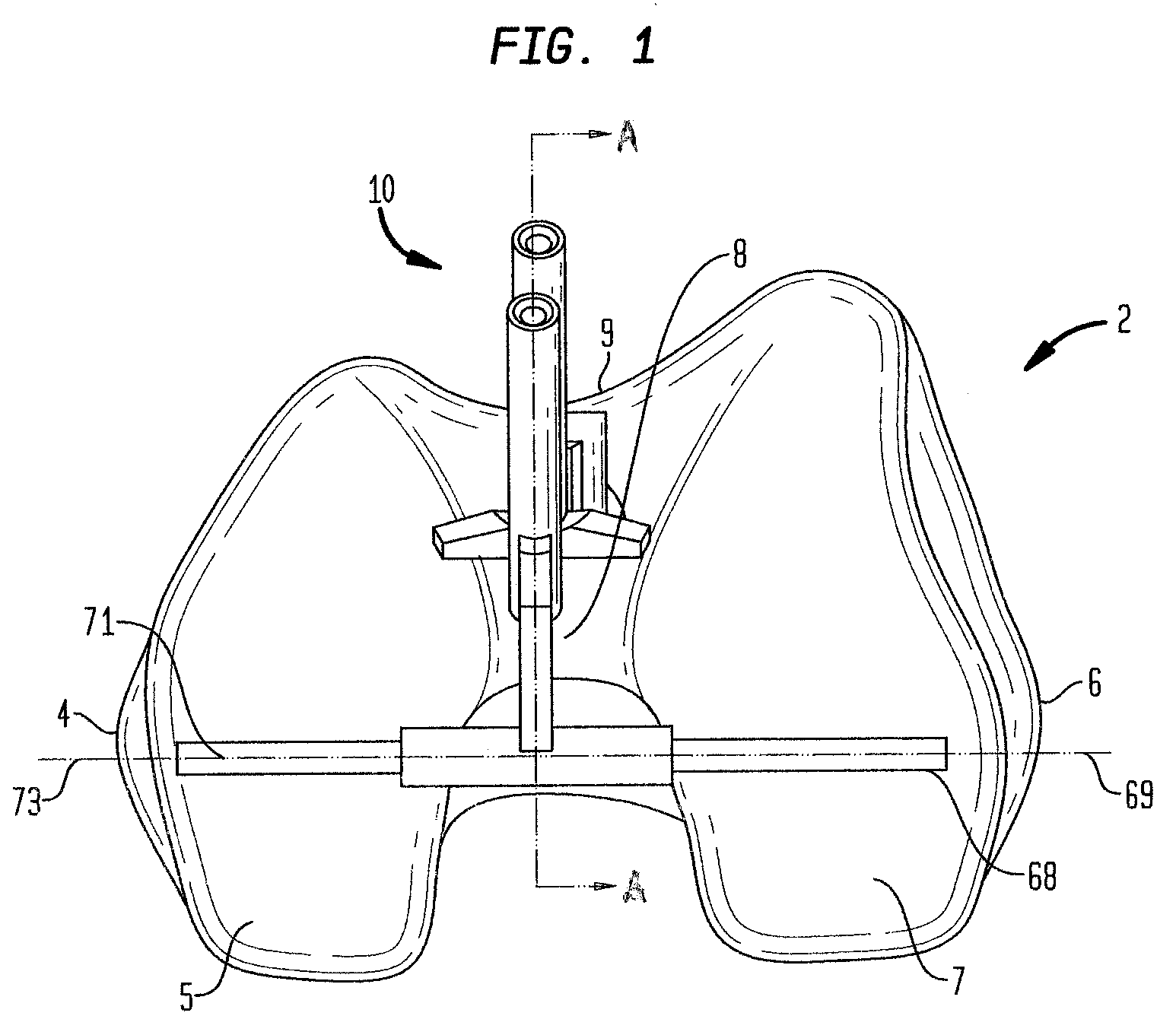
[0033]The systems and methods that are described herein generally include the use of a family of multiple sized trochlear prostheses, a combination drill-and-alignment guide corresponding to each prosthesis, a flexible sizing membrane corresponding to each prosthesis, a series of guide pins to insert in guide holes of the combination drill-and-alignment guide, and a series of bone cutting instruments or reamers corresponding to specific sections of each prosthesis.

[0034]Ref...


PUM


Abstract

The present invention relates to systems and methods for preparing the trochlear groove of a patient's femur to receive a prosthesis thereon. In the system, a combination drill-and-alignment guide includes at least a proximal and intermediate section, and preferably also includes a distal section. Guide holes for receiving guide pins therein are located in the proximal and distal sections of the guide. After the guide is positioned using at least one of several visual and/or tactile references in the system, the guides pins are placed through the guide holes of the guide and into bone. The guide may then be removed and replaced by cannulated reamers that are rotated and used to resect a predetermined amount of bone around the guide pins. A prosthesis having at least a portion of an outer surface that substantially matches the trochlear groove of the patient in a pre-degenerated state is then implanted on the resected bone.

Description

FIELD OF THE TECHNOLOGY[0001]The present invention relates to an apparatus and method for preparing the trochlear groove of a patient's femur to receive a prosthesis thereon, and in particular, relates to positioning a guide on the patient's femur that aides in the resection of the femur such that the prosthesis may be implanted on the resected bone.BACKGROUND OF THE INVENTION[0002]Patello-femoral joint disease is a condition in which the articular cartilage of the patella and / or the femoral trochlear groove is eroded due to osteoarthritis resulting in some cases in severe anterior knee pain. For patients with isolated patello-femoral joint disease who otherwise show no evidence of the disease present in the tibiofemoral joint, or for patients with a history of chronic patella dislocations, a patello-femoral joint replacement offers a beneficial alternative to total joint replacement. Moreover, a patello-femoral joint replacement provides pain relief or improved patella tracking whi...

Claims


Application Information

Patent Timeline
Patent Type & Authority Applications(United States)
IPC IPC(8): A61B17/58
CPCA61F2/3877A61B17/1764A61B17/1739A61B2017/320052A61B17/90
Inventor COLLAZO, CARLOS E.SERVIDIO, DAMONSCHELLER, ARNOLD DOUGLAS
Owner STRYKER CORP
Why Eureka
Try Eureka