System and method for damping vibration in a drill string using a magnetorheological damper

a magnetorheological damper and drill string technology, which is applied in the direction of drilling/well accessories, sealing/packing, and surveying, can solve the problems of reducing the penetration rate of the drill bit into the drilling surface, affecting the drilling effect, and inducing substantial vibration and shock into the drill string, so as to reduce alter the viscosity of the mr fluid. , the effect of reducing the induced remanent magnetic field

Active Publication Date: 2010-09-09
APS TECH
View PDF33 Cites 41 Cited by
  • Summary
  • Abstract
  • Description
  • Claims
  • Application Information

AI Technical Summary

Benefits of technology

[0011]In one embodiment, the invention is applied to a damping system for damping vibration in a down hole portion of a drill string in which the damping system comprises an MR valve containing an MR fluid subjected to a magnetic field created by at least one coil. In this embodiment, the invention includes a method of operating the MR valve comprising the steps of: (a) energizing the coil of the MR valve for a first period of time so as to create a first magnetic field that alters the viscosity of the MR fluid, the first magnetic field being sufficient to induce a first remanent magnetization in at least one component of the MR valve, the first remanent magnetization being at least about 12,000 Gauss; (b) substantially de-energizing the coil for a second period of time so as to operate the MR valve using the first remanent magnetization in the at least one component of said MR valve to create a second magnetic field that alters the viscosity of said MR fluid; (c) subjecting the at least one component of the MR valve to a demagnetization cycle over a third period of time so as to reduce the first remanent magnetization of the at least one component of said MR valve to a second remanent magnetization; and (d) operating said MR valve for a third period of time after the demagnetization cycle in step (c). Preferably, the magnetic field associated with the first remanent magnetization is sufficient to magnetically saturate said MR fluid. The value of the remanent magnetization can be measured using a sensor and the coil re-energized when the value drops below a specified minimum.
[0012]In another embodiment, a valve assembly for damping vibration of a drill bit is provided, comprising (a) a first member capable of being mechanically coupled to the drill bit so that the first member is subjected to vibration from the drill bit; (b) a supply of magnetorheological fluid; (c) a second member mechanically coupled to the first member so that the second member can move relative to the first member, the first and second members defining a first chamber and a second chamber for holding the magnetorheological fluid, a passage placing the first and second chambers in fluid communication; (d) at least one coil proximate to the passage so that the magnetorheological fluid can be subjected to a magnetic field generated by the at least one coil when the coil is energized; (e) at least a portion of one of said first and second members being capable of having induced therein a remanent magnetic field in response to said magnetic field generated by said at least one coil that is sufficient to operate said MR valve when said coil is de-energized, said portion of said first and second members in which said remanent magnetic field is induced being made from a material have a maximum remanent magnetization of at least about 12,000 Gauss. Preferably, the valve assembly includes means for demagnetizing the portion of said one of the first and second members so as to reduce the induced remanent magnetic field. The valve assembly may include a sensor for measuring the value of the remanent magnetization and means for re-energizing the coil when the value drops below a specified minimum.

Problems solved by technology

The drilling environment, and especially hard rock drilling, can induce substantial vibration and shock into the drill string.
Such vibration can result in premature failure of the various components of the drill string.
Substantial vibration also can reduce the rate of penetration of the drill bit into the drilling surface, and in extreme cases can cause a loss of contact between the drill bit and the drilling surface.
Reducing the weight-on-bit or the rotary speed of the drill bit also usually reduces drilling efficiency.
Operating the drill bit away from its design point can reduce the performance and the service life of the drill bit.
Operating the shock sub outside of these conditions can render the shock sub ineffective, and in some cases can actually increase drill string vibrations.
Moreover, shock subs and isolators usually isolate the portions of the drill string up-hole of the shock sub or isolator from vibration, but can increase vibration in the down-hole portion of the drill string, including the drill bit.
Unfortunately, the inventors have found that the minimum level of damping achievable using such MR valves is compromised by the fact that energizing the coil can result in a low level of permanent magnetization of the valve components.
A problem experienced by prior art MR valves is that using a coil to maintain the magnetic field requires a considerable amount of electrical energy.
Consequently, turbine alternators, which are expensive and costly to maintain, are typically required to power the coils.

Method used


Image

  • System and method for damping vibration in a drill string using a magnetorheological damper
  • System and method for damping vibration in a drill string using a magnetorheological damper
  • System and method for damping vibration in a drill string using a magnetorheological damper

Examples


Embodiment Construction

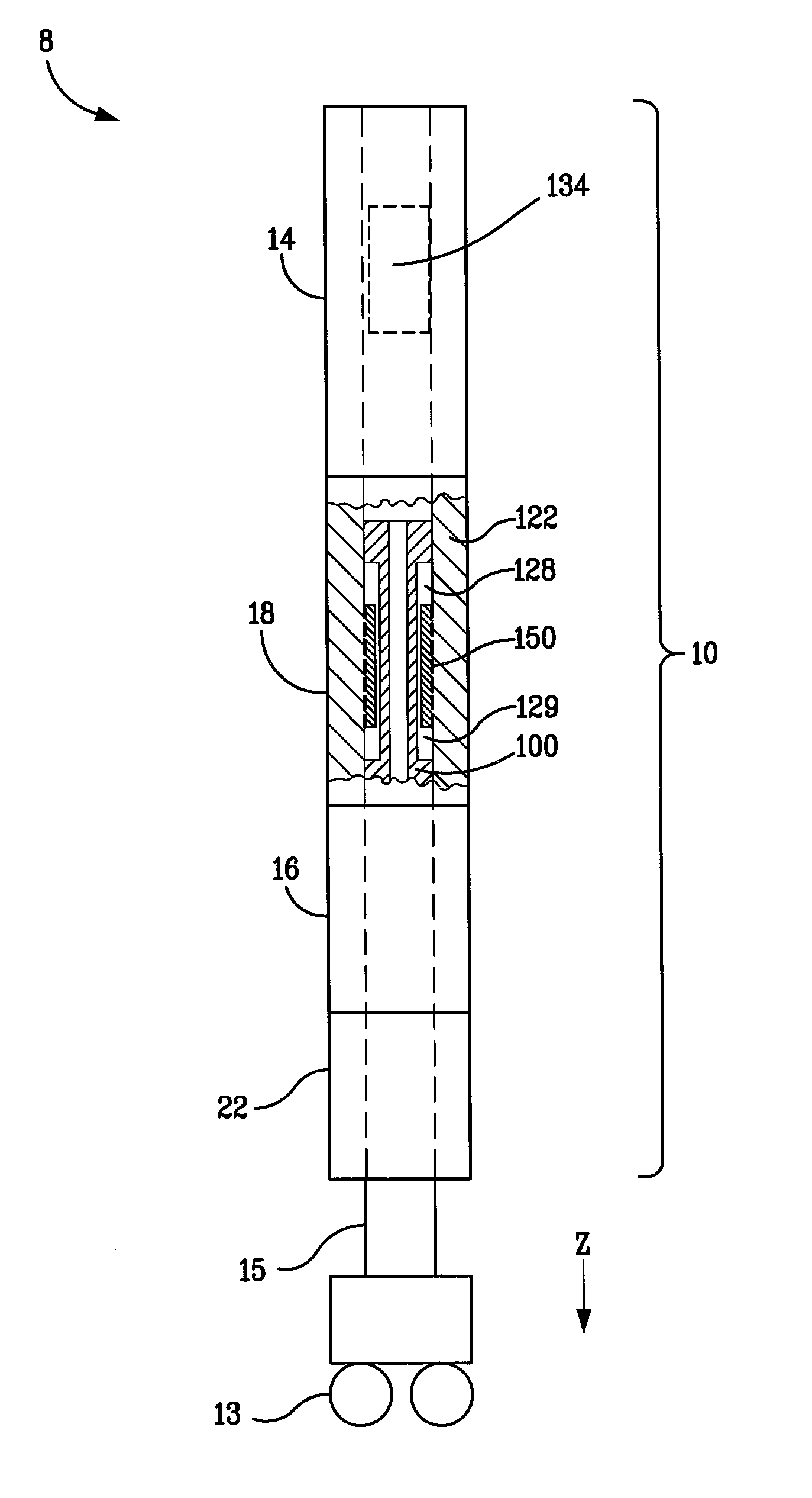
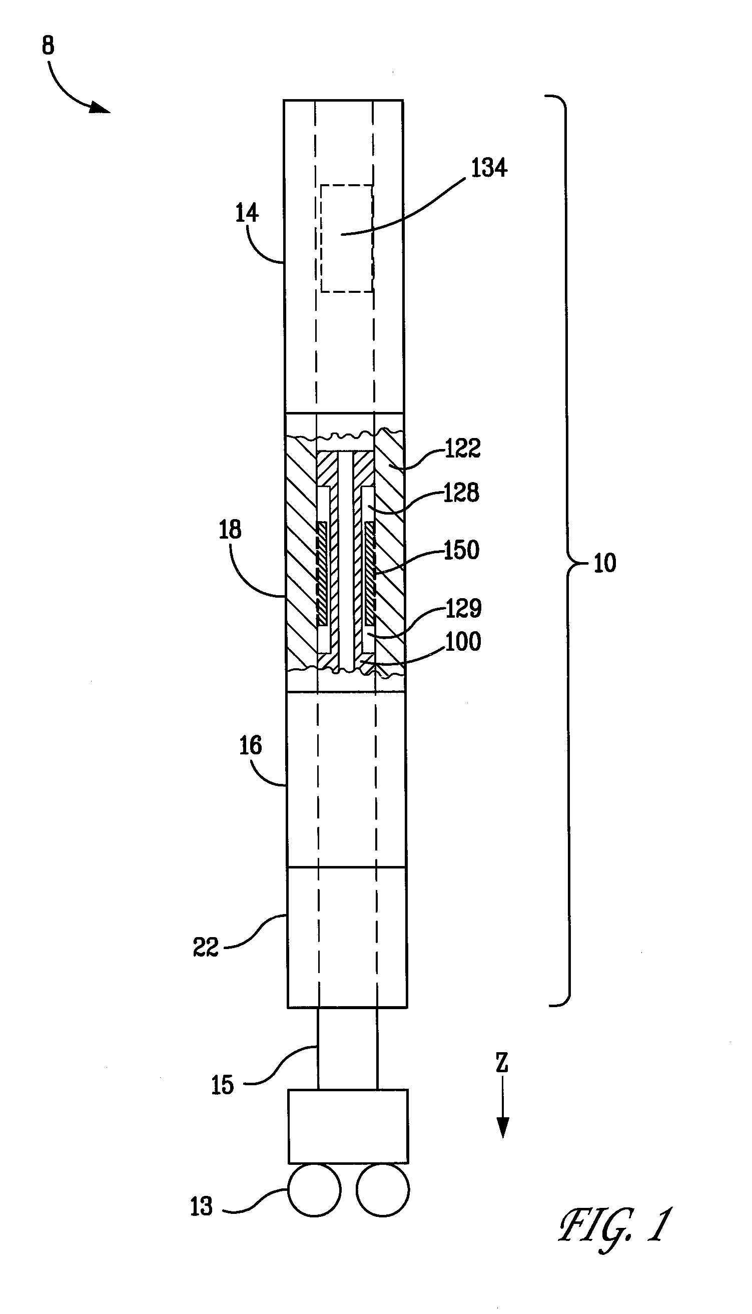
[0029]The figures depict a preferred embodiment of a vibration damping system 10. As shown in FIG. 1, the vibration damping system 10 can be incorporated into a downhole portion of a drill string 8 to dampen vibration of a drill bit 13 located at a down-hole end of the drill string.

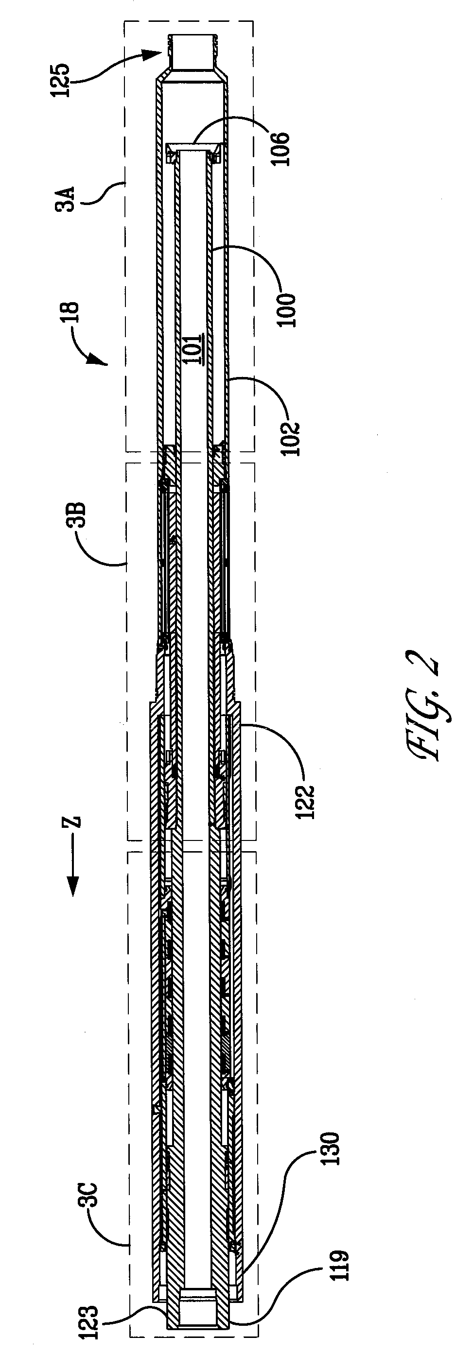
[0030]The downhole portion of the drill string 8 includes a power module 14. The vibration damping system 10 comprises a torsional bearing assembly 22 and a spring assembly 16, each of which is discussed more fully in the aforementioned U.S. Pat. No. 7,219,752. In addition, located between the spring assembly 16 and the power module 14 is a magnetorheological (“MR”) valve assembly 18. The MR valve assembly 18 and the spring assembly 16 can produce axial forces that dampen vibration of the drill bit 13. The magnitude of the damping force can be varied by the MR valve assembly 18 in response to the magnitude and frequency of the drill bit vibration after the drill bit has temporarily ceased operation, for e...


PUM


Abstract

A system for damping vibration in a drill string can include a magnetorheological fluid valve assembly having a supply of a magnetorheological fluid, a first member, and a second member capable of moving in relation to first member in response to vibration of the drill bit. The first and second members define a first and a second chamber for holding the fluid. Fluid can flow between the first and second chambers in response to the movement of the second member in relation to the first member. The valve assembly can also include a coil for inducing a magnetic field that alters the resistance of the magnetorheological fluid to flow between the first and second chambers, thereby increasing the damping provided by the valve. A remanent magnetic field is induced in one or more components of the magnetorheological fluid valve during operation that can be used to provide the magnetic field for operating the valve so as to eliminate the need to energize the coils during operation except temporarily when changing the amount of damping required, thereby eliminating the need for a turbine alternator power the magnetorheological fluid valve. A demagnetization cycle can be used to reduce the remanent magnetic field when necessary.

Description

[0001]Pursuant to 35 U.S.C. §202(c), it is acknowledged that the U.S. government may have certain rights to the invention described herein, which was made in part with funds from the Deep Trek program of the U.S. Department of Energy National Energy Technology Laboratory, Grant Number DE-FC26-02NT41664.[0002]The present invention relates to underground drilling, and more specifically to a system and a method for damping vibration that occurs in a drill string during drilling operations using a MR fluid.BACKGROUND OF THE INVENTION [0003]Underground drilling, such as gas, oil, or geothermal drilling, generally involves drilling a bore through a formation deep in the earth. Such bores are formed by connecting a drill bit to long sections of pipe, referred to as a “drill pipe,” so as to form an assembly commonly referred to as a “drill string.” The drill string extends from the surface to the bottom of the bore.[0004]The drill bit is rotated so that the drill bit advances into the earth...

Claims


Application Information

Patent Timeline
Patent Type & Authority Applications(United States)
IPC IPC(8): E21B41/00E21B7/00E21B34/06
CPCE21B17/073E21B17/07
Inventor WASSELL, MARK ELLSWORTHBURGESS, DANIEL E.BARBELY, JASON R.
Owner APS TECH
Why Eureka
Try Eureka