Connection assembly for ultra high pressure liquid chromatography

a technology of connection assembly and liquid chromatography, which is applied in the direction of separation processes, instruments, manufacturing tools, etc., can solve the problems of wasting time and inefficiency in replacing columns in conventional lc systems, affecting the efficiency of separation, and affecting the quality of separation

Inactive Publication Date: 2010-09-09
IDEX HEALTH & SCI
View PDF16 Cites 48 Cited by
  • Summary
  • Abstract
  • Description
  • Claims
  • Application Information

AI Technical Summary

Benefits of technology

[0025]In still another embodiment, a method of assembling a fitting assembly is provided, by which an operator can easily connect tubing to a component or fitting of an LC or other AI system. In one embodiment, an operator can insert tubing through the passageways of a nut, a double-headed ferrule, and a fitting, such as those described above and in more detail below. The operator can then rotate the nut and the fitting relative to one another, such as by rotating the fitting in a clockwise motion when viewed from the second end of the fitting. Alternatively, the operator can turn th

Problems solved by technology

If the connection is too weak, it may leak.
Because the types of solvents that are sometimes used as the mobile phase are often toxic and because it is often expensive to obtain and/or prepare many samples for use, any such connection failure is a serious concern.
Moreover, the time involved in disconnecting and then connecting a column (or other component) is unproductive because the LC system is not in use and the operator is engaged in plumbing the system instead of preparing samples or other more productive activities.
Hence, the replacement of a column in a conventional LC system involves a great deal of wasted time and inefficiencies.
More recently, however, it has been realized that the use of stainless steel components in a LC system have potential drawbacks in situations involving biological samples.
This presents problems because the detector's measurements (and thus the chromatogram) of a given sample may not accurately reflect the sample if some of the sample's ions remain in the tubing and do not pass the detector.
Perhaps of even greater concern, however, is the fact that ions from the stainless steel tubing may detach from the tubing and flow past the detector, thus leading to potentially erroneous results.
One reason for this is that a valve having a large volume will contain a relatively large volume of liquid, an

Method used


Image

  • Connection assembly for ultra high pressure liquid chromatography
  • Connection assembly for ultra high pressure liquid chromatography
  • Connection assembly for ultra high pressure liquid chromatography

Examples


Embodiment Construction

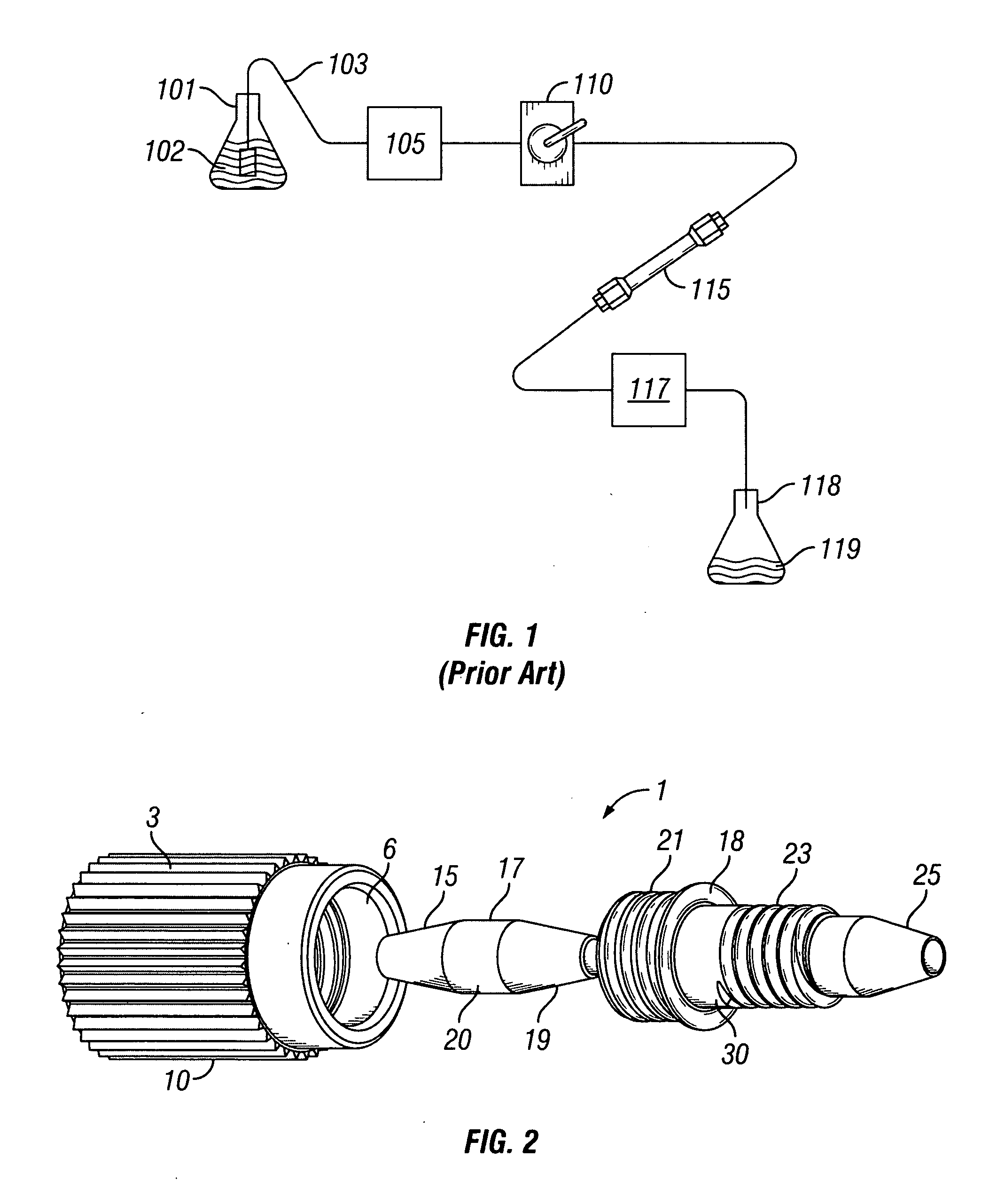
[0034]In FIG. 1, a block diagram of the essential elements of a conventional LC system is provided. A reservoir 101 contains a solvent or mobile phase 102. Tubing 103 connects the mobile phase 102 in the reservoir 101 to a pump 105. The pump 105 is connected to a sample injection valve 110 which, in turn, is connected via tubing to a first end of a guard column (not shown). The second end of the guard column (not shown) is in turn connected to the first end of a primary column 115. The second end of the primary column 115 is then connected via tubing to a detector 117. After passing through the detector 117, the mobile phase 102 and the sample injected via injection valve 110 are expended into a second reservoir 118, which contains the chemical waste 119. As noted above, the sample injection valve 110 is used to inject a sample of a material to be studied into the LC system. The mobile phase 102 flows through the tubing 103 which is used to connect the various elements of the LC sys...


PUM

PropertyMeasurementUnit
Forceaaaaaaaaaa
Angleaaaaaaaaaa
Biocompatibilityaaaaaaaaaa

Abstract

A fitting assembly having a double-headed ferrule, a nut, and a fitting that may be assemble or dissembled by an operator. The fitting assembly includes a nut with first and second ends, with the second end have an internally tapered portion adapted to receive the first end of a ferrule, and further includes a fitting with a first end having an internally tapered portion adapted to receive the second end of the ferrule and a second end adapted to be removably connected to a component or fitting of a liquid chromatography system. The nut, ferrule and fitting of the fitting assembly have passageways therethrough for receiving and removably holding tubing.

Description

FIELD OF THE INVENTION[0001]This invention relates generally to an assembly for use in connecting components of liquid chromatography systems, and relates more particularly to an assembly well-suited for allowing quick connections and disconnections of components in liquid chromatography systems used in ultra-high pressure liquid chromatography.BACKGROUND OF THE INVENTION[0002]Liquid chromatography (LC) is a well-known technique for separating the constituent elements in a given sample. In a conventional LC system, a liquid solvent (referred to as the “mobile phase”) is introduced from a reservoir and is pumped through the LC system. The mobile phase exits the pump under pressure. The mobile phase then travels via tubing to a sample injection valve. As the name suggests, the sample injection valve allows an operator to inject a sample into the LC system, where the sample will be carried along with the mobile phase.[0003]In a conventional LC system, the sample and mobile phase pass t...

Claims


Application Information

Patent Timeline
IPC IPC(8): B01D15/08F16L21/06B23P11/00
CPCB01D15/125B01D15/22F16L49/06Y10T29/49963G01N2030/085G01N30/6039
Inventor ELLIS, SCOTT J.SANDERS, TROY N.
Owner IDEX HEALTH & SCI
Why Eureka
Try Eureka