Gas-insulated circuit breaker

a circuit breaker and gas-insulated technology, applied in the direction of air-break switch, high-tension/heavy-dress switch, electrical apparatus, etc., can solve the problems of difficult to reduce the mechanical compression effect relatively, the temperature gradient is extremely steep, and the interruption of electric current, etc., to achieve excellent opening performance, reduce the effect of structural cooling and less impact on the environmen

Inactive Publication Date: 2010-09-09
KK TOSHIBA
View PDF12 Cites 13 Cited by
  • Summary
  • Abstract
  • Description
  • Claims
  • Application Information

AI Technical Summary

Benefits of technology

[0048]The present invention has been made to solve the above problems. The object of the present invention is to provide a gas-insulated circuit breaker that can contribute to extending product life and reducing impact on the environment, lead to downsizing and lower costs, and achieve high opening performance and high reliability.
[0050]According to the present invention having the above configuration, since the inside-nozzle insulating member is disposed in the insulating nozzle, the high-temperature arc generated at the time of the opening operation is in contact not only with the inner wall section of the insulating nozzle but with the outer wall section of the inside-nozzle insulating member. Therefore, the arc is cooled down structurally. Thus, it is possible to secure excellent opening performance even as the lower-cooling-performance gas is used, and the gas that has less impact on the environment can be used. Therefore, while the opening performance is maintained at a satisfactory level, harmony with the environment can be achieved.
[0051]Moreover, since the inside-nozzle insulating member is incorporated in the insulating nozzle, the cross-section area of the gas passage is made smaller in size. Therefore, it is possible to reduce the amount of the gas flow exhausted from the pressure accumulation space, thereby making more use of the arc heat in increasing the pressure of the pressure accumulation space. In addition, since the inner diameter of the insulating nozzle need not be narrowed, it is unnecessary to reduce the members in diameter inside the insulating nozzle.
[0052]As a result, it is possible to secure the durability of the members inside the insulating nozzle and extend product life. Moreover, since nothing is reduced to extremely small size in diameter, the generation of a high electric field is avoided. The separation distance and the separating speed are suppressed, and it is possible to downsize and reduce driving energy. Furthermore, the inside-nozzle insulating member that brings about such effects has a simple structure and is co-axial with respect to the insulating nozzle. The number of members of the inside-nozzle insulating member is far smaller than a gas passage adjustment mechanism having an iris diaphragm structure. In addition, the inside-nozzle insulating member has no movable parts. Therefore, production costs are extremely low, and an excellent level of economic efficiency is achieved.
[0053]According to the present invention, the gas-insulated circuit breaker has an extremely simple structure in which the co-axial inside-nozzle insulating member is disposed in the insulating nozzle, contributing to extending product life and reducing impact on the environment, leading to downsizing and lower costs, and achieving improved opening performance and high reliability.

Problems solved by technology

The temperature gradient is extremely steep.
Moreover, the fact that the temperature of the arc 8 reaches several tens of thousands K around an over-current peak also contributes to the interruption of electric current.
Moreover, if the thermal compression effect of the arc 8 is used less frequently, then it becomes difficult to reduce the mechanical compression effect relatively.
As a result, it becomes difficult to achieve such effects, like a reduction in driving force or preventing an increase in the amount of contained gas, which lead to the downsizing of the device.
However, if the passage cross-section area S1 of the gas passage 6a is simply made small, new problems arise.
However, the following problems with the conventional puffer type gas-insulated circuit breakers have been pointed out.
However, these days, the use of SF6 gas entails the following problems.
Therefore, the problem is that the cooling effect of the arc 8 decreases.
The problem is, therefore, that as for the members that work to suppress the amount of the gas flow from the insulating nozzle, production costs are high.

Method used


Image

  • Gas-insulated circuit breaker
  • Gas-insulated circuit breaker
  • Gas-insulated circuit breaker

Examples


first embodiment

(1) First Embodiment

Configuration

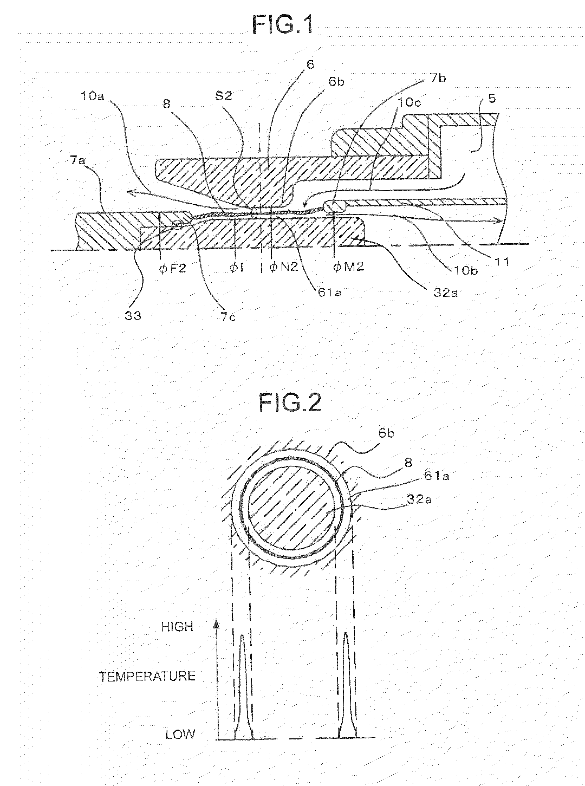
[0064]A first embodiment of the present invention will be described with reference to FIGS. 1 and 2. FIG. 1 illustrates a situation near an arc during the opening operation of a gas-insulated circuit breaker. Since the components of the gas-insulated circuit breaker are symmetrical about a symmetry axis, FIG. 1 illustrates only the upper half of the gas-insulated circuit breaker above the central axis.

[0065]The portion of the gas-insulated circuit breaker not illustrated in FIG. 1 have the same configuration as the conventional gas-insulated circuit breaker of a type that actively makes use of the heat energy of the arc 8 to increase the pressure of the puffer chamber 5. A diagram on the upper side of FIG. 2 is a cross-sectional view of the throat section 6b of the insulating nozzle 6 along the radial direction, and a diagram on the lower side illustrates the temperature distribution inside the throat section 6b.

[0066]The most different feature in c...

second embodiment

(2) Second Embodiment

Configuration

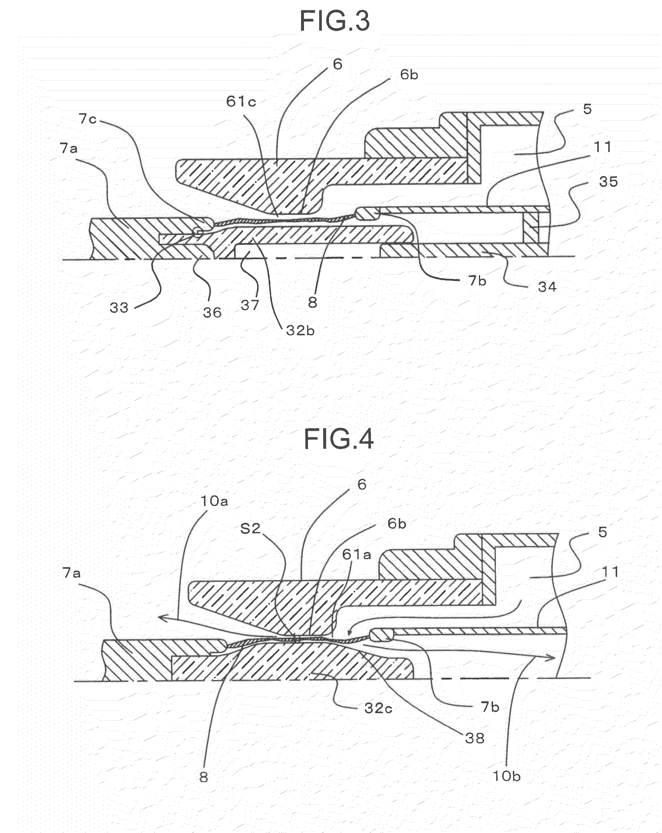
[0088]A second embodiment of the present invention will be described in detail with reference to FIG. 3. FIG. 3 illustrates a situation near an arc during the opening operation of a gas-insulated circuit breaker. Since the components of the gas-insulated circuit breaker are symmetrical about a symmetry axis, FIG. 3 illustrates only the upper half of the gas-insulated circuit breaker above the central axis.

[0089]The configuration of the second embodiment is basically the same as that of the first embodiment except for the following feature. That is, as shown in FIG. 3, an electric field weakening shield 36 is provided at the center of the front end section of the fixed arcing contact 7a. The electric field weakening shield 36 is embedded in an inside-nozzle insulating member 32b. Incidentally, the reference numeral 35 denotes a rod support attached to the hollow rod 11.

[0090]According to the second embodiment, the inside-nozzle insulating member 32b ...

third embodiment

(3) Third Embodiment

Configuration

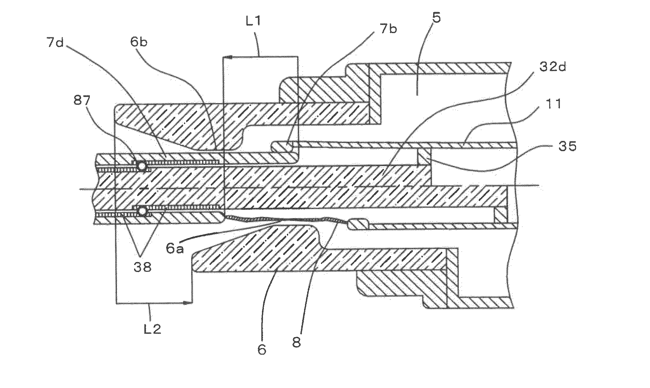
[0104]A third embodiment of the present invention will be described with reference to FIG. 4. FIG. 4 illustrates a situation near an arc during the opening operation of a gas-insulated circuit breaker. Since the components of the gas-insulated circuit breaker are symmetrical about a symmetry axis, FIG. 4 illustrates only the upper half of the gas-insulated circuit breaker above the central axis.

[0105]As the characteristic configuration of the third embodiment, the gas-insulated circuit breaker is equipped with an inside-nozzle insulating member 32c having a taper 38. The taper 38 is thick in diameter around the center of the inside-nozzle insulating member 32c and is formed in a curve so as to become thinner toward the end section.

[0106]That is, the inside-nozzle insulating member 32c on which the taper 38 is formed is not uniform in diameter along the axial direction. Therefore, the gas passage 61c of the insulating nozzle 6 of the third embodiment ...


PUM


Abstract

A gas-insulated circuit breaker has a sealed container filled with gas; a pair of contacts so constructed as to be connected and separated each other in the sealed container; gas flow generation means for blasting the gas on an arc generated when the contacts are separated, the gas flow generation means including: an accumulation space, pressure increasing means for increasing the pressure of the pressure accumulation space, a gas passage connecting the pressure accumulation space to the arc, and an insulating nozzle that controls the flow of the gas from the pressure accumulation space to the arc; an inside-nozzle insulating member disposed co-axially with the insulating nozzle. The arc is generated in a space between an inner wall section of the insulating nozzle and an outer wall section of the inside-nozzle insulating member, and the gas flows in the space.

Description

CROSS REFERENCE TO RELATED APPLICATION[0001]This application is based upon and claims the benefits of priority from the prior Japanese Patent Application No. 2009-54226, filed in the Japanese Patent Office on Mar. 6, 2009, the entire content of which is incorporated herein by reference.BACKGROUND OF THE INVENTION[0002]The present invention relates to a puffer type gas-insulated circuit breaker that extinguishes an arc by blasting an insulating gas on the arc, and particularly to a gas-insulated circuit breaker having the improved structure of an insulating nozzle that blasts the insulating gas.[0003]The gas-insulated circuit breaker is a device in which a pair of contacts is disposed inside a sealed container filled with insulating gas, and is often used as an on-off switch for electric current in an electric power transmission and distribution system. Hereinafter, an example of a conventional puffer type gas-insulated circuit breaker will be described in detail with reference to FI...

Claims


Application Information

Patent Timeline
Patent Type & Authority Applications(United States)
IPC IPC(8): H01H33/72H01H33/04
CPCH01H33/7076H01H2033/888H01H2033/566
Inventor UCHII, TOSHIYUKIMORI, TADASHISHINKAI, TAKESHI
Owner KK TOSHIBA
Why Eureka
Try Eureka