Heat insulated container

a technology of insulated containers and containers, applied in the field of insulating containers, can solve the problem that the configuration only applies to labels, and achieve the effects of improving the heat releasing effect, eliminating the blocking problem, and improving the transport

Active Publication Date: 2010-09-09
TOKAN KOGYO CO LTD
View PDF12 Cites 20 Cited by
  • Summary
  • Abstract
  • Description
  • Claims
  • Application Information

AI Technical Summary

Benefits of technology

[0010]In the present invention, the container is made into a shape having a low stack height and being free from blocking, while the container is formed or shipped. For example, the container can be deformed into an insulating holder by having the slit forming section of the exterior sleeve project outwardly in such a manner that hot water or high-temperature drink is poured into the container, the container is heated, or the container is subjected to microwave by a kitchen microwave, for example, when the container is used as a table ware or a drink container. Further, in the present invention, an improved heat releasing effect can be produced because of a space formed between the exterior sleeve and a container main body, such that it is no more necessary to move the exterior sleeve by hands.
[0011]The above described shrink-deformation of the exterior sleeve can be achieved not only at the time of using the container but at any time it is necessary if the exterior sleeve is heated or subjected to microwave, for example, at the time of packaging the container.
[0012]Further, the exterior sleeve is provided with the slit forming section, which eliminates a necessity to form an air space between the slit forming section and the container main body before deformation. Therefore, the container can be made into a stack height identical to that of the general containers, resulting in eliminating the blocking problem.
[0013]Still further, since the stack height of the container becomes lower and constant, an improved transport effect can be produced, a mechanical adaptability improves when separating the containers, and a handling ability of the container improves.
[0014]A shape of the insulating holder can be changed according to shapes of the slits of the slit forming section.
[0015]Further, when the exterior sleeve is formed into a cylindrical shape, the slit forming section includes the outside bonding portion and notches formed on the inside bonding portion in a corresponding manner, and a portion of the shrink-deformable film corresponding to the outside bonding portion is directly heated through the container main body, and thereby the slit forming section formed on the outside bonding portion also can securely be projected downwardly.

Problems solved by technology

However, the label has such a configuration that a deformation caused by heat-shrinkage is controlled by a cut line having a transverse H-shape and therefore the configuration has a drawback that it is only applicable to labels.

Method used


Image

  • Heat insulated container
  • Heat insulated container
  • Heat insulated container

Examples


first exemplary embodiment

[0062][Cup-shaped Container]

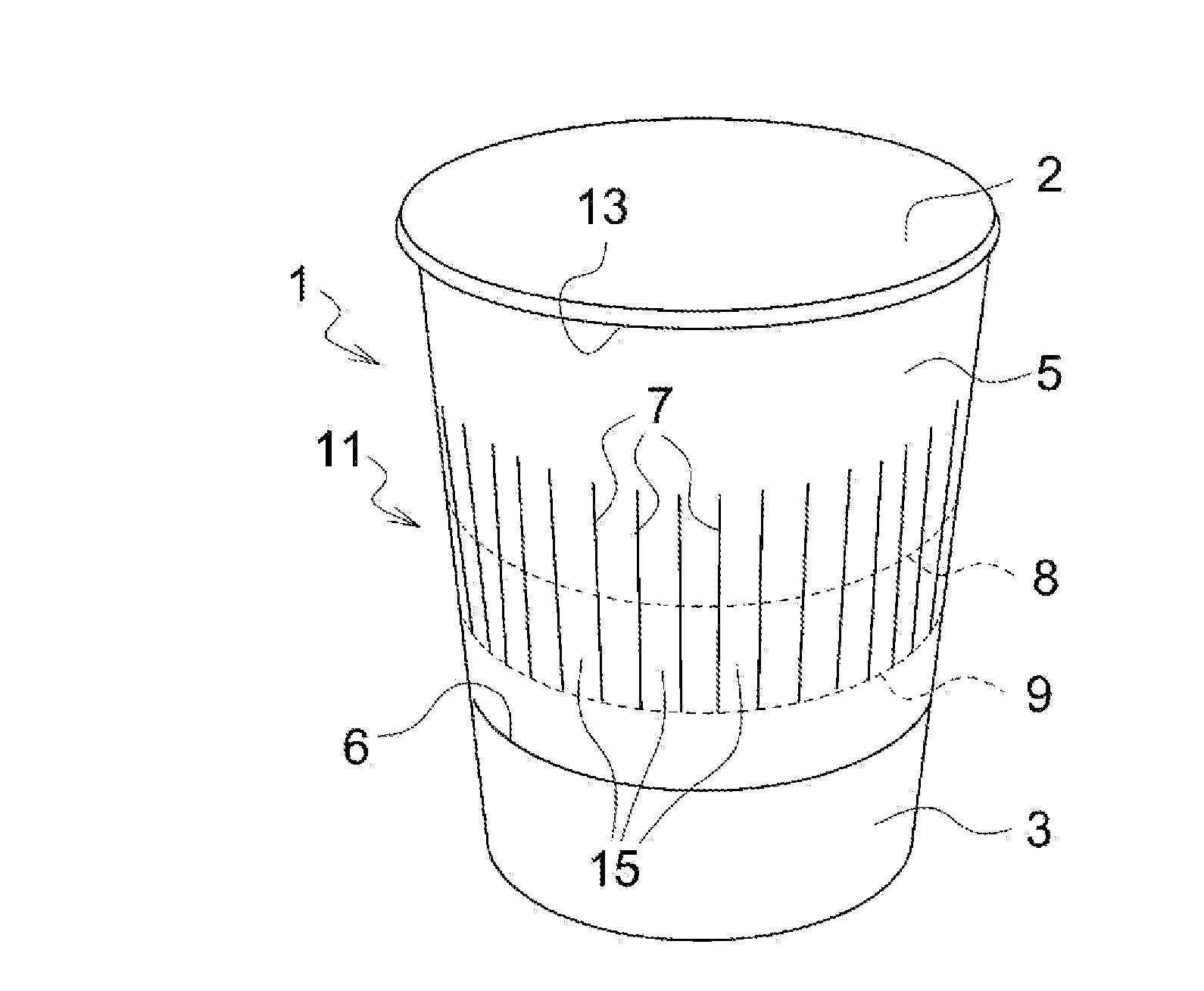
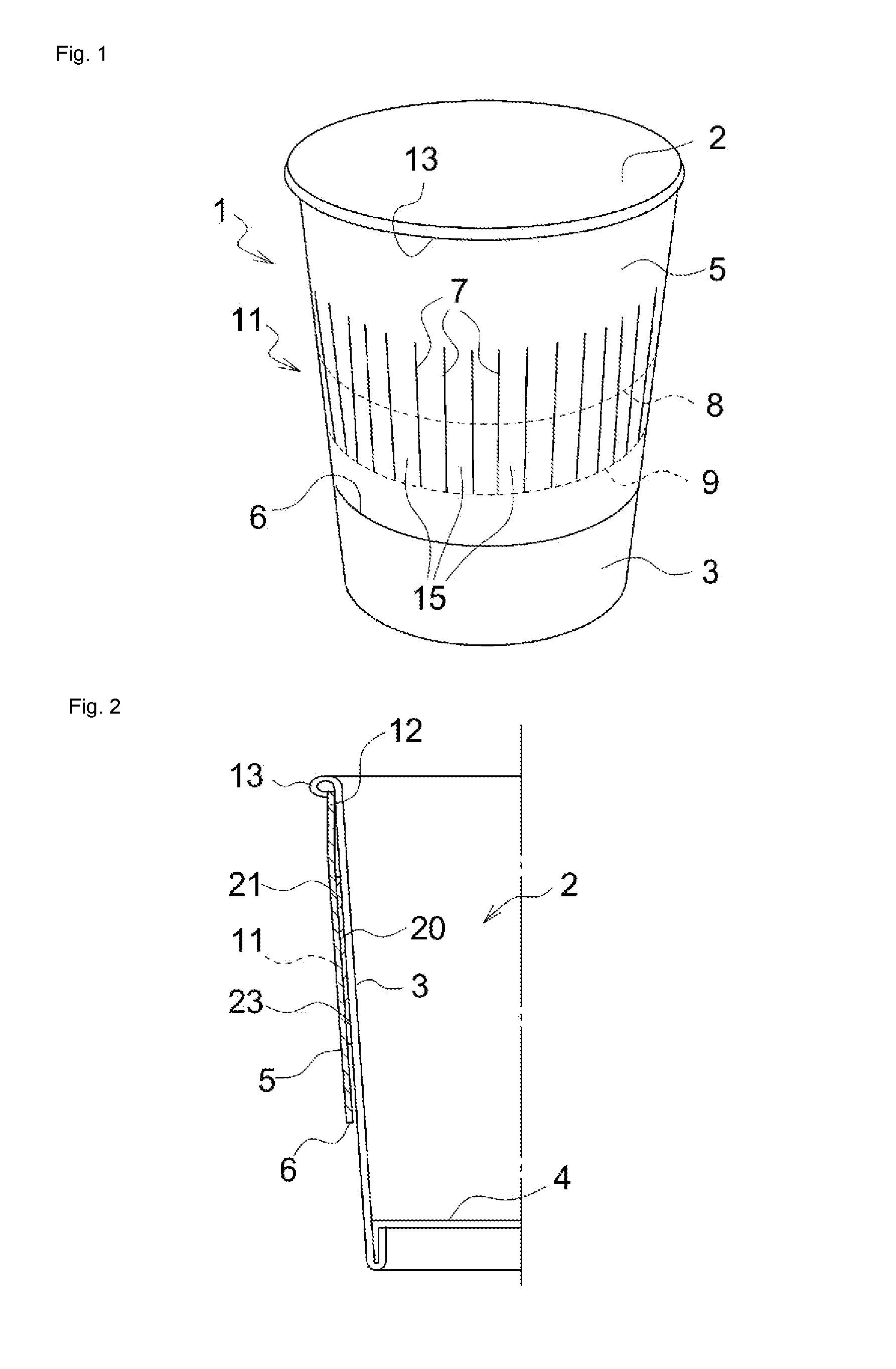
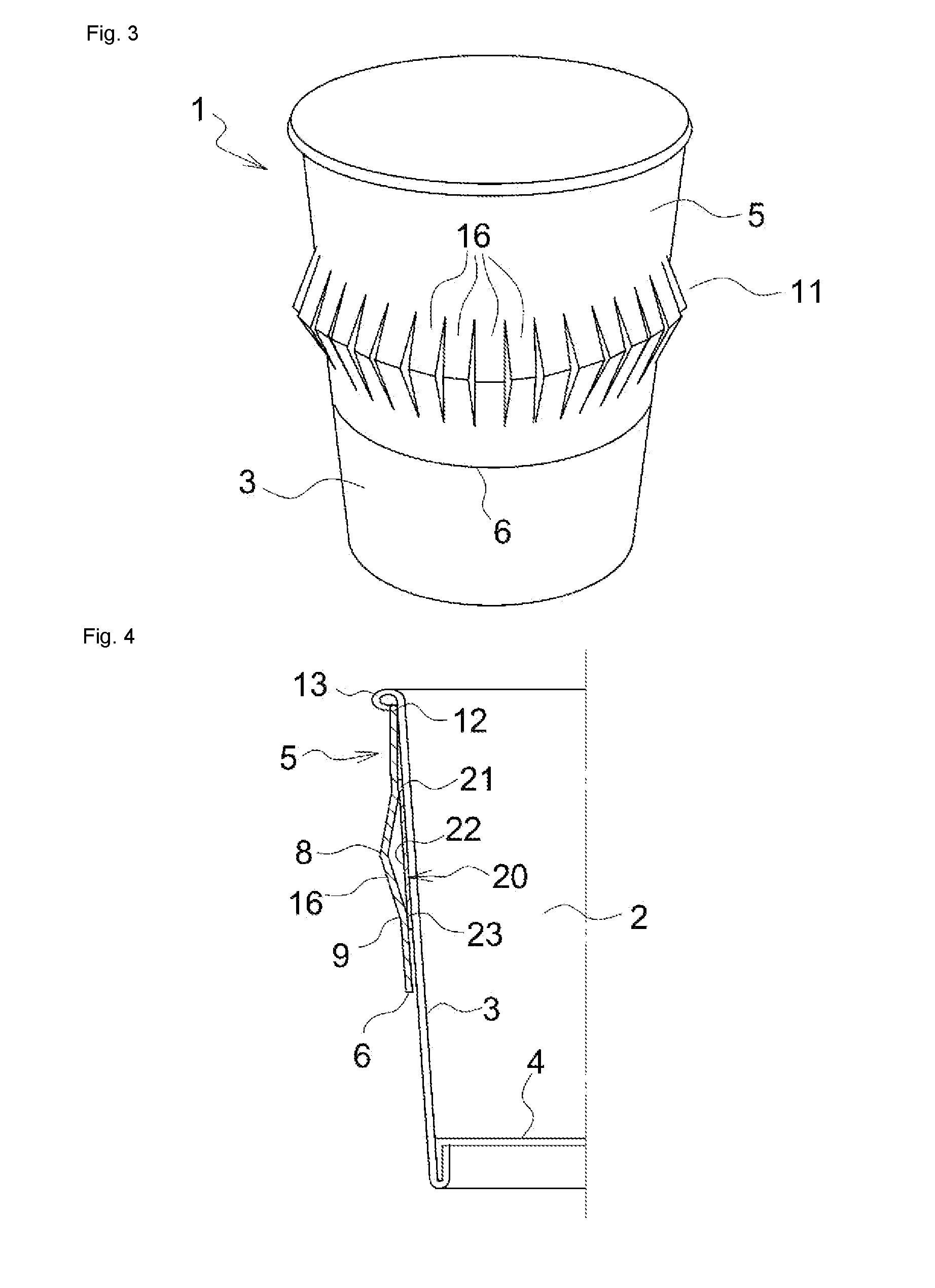
[0063]A cup-shaped container 1 as illustrated in FIGS. 1 through 4 comprises a cup-shaped container main body 2 including a body portion wall 3 having a water-resistance interior surface and a bottom portion wall 4, and an exterior sleeve 5.

[0064]The exterior sleeve 5 includes a slit forming section 11 having a group of a plurality of slits provided over a predetermined area in a height direction of the container, and being fit onto an outer circumferential portion of the body portion wall 3 so as to cover the body portion wall.

[0065]In the present exemplary embodiment, examples of the cup-shaped container 1 include a cup-shaped container formed of only a paper material, a cup-shaped container formed of a paper material laminated with a synthetic resin film, a cup-shaped container formed of a paper material impregnated with a synthetic resin, a cup-shaped container formed of a paper material laminated with a synthetic resin film or a metallic foil, and a ...

second exemplary embodiment

[0100]In the exterior sleeve 5, a shape of the ruled line formed on the strip of paper 15 is not limited to that as illustrated in the above described exemplary embodiment but, for example, as illustrated in FIG. 8, the ruled lines may be provided alternately for every adjacent strips of paper.

[0101]More specifically, a strip of paper 15a including a ruled line for valley fold 9a which is formed between upper portions of the slits 7 and a ruled line for mountain fold 8a which is formed lower than the ruled line for valley fold 9a spaced by a predetermined distance, and a strip of paper 15b including a ruled line for valley fold 9b which is formed between lower portions of the slits 7 and a ruled line for mountain fold 8b which is formed higher than the ruled line for valley fold 9b spaced by a predetermined distance are arranged alternately.

[0102]Meantime, the ruled line for mountain fold 8a of the strip of paper 15a and the ruled line for mountain fold 8b of the strip of paper 15b ...

third exemplary embodiment

[0105]Four ruled lines are formed on every strips of paper 15 in FIG. 9 as they are disclosed in FIGS. 6 and 7 of the Patent Literature 1 and in FIGS. 6 and 7 of the Patent Literature 2.

[0106]More specifically, each strip of paper 15 of the cup-shaped container 1 of the present exemplary embodiment includes a first ruled line for valley fold 9a′ with a predetermined angle (an angle of 45 degrees in the illustration) so as to form a declining line from an upper end of the slit 7, a second ruled line for mountain fold 8a′ which is formed in parallel below the first ruled line for valley fold 9a′, the first ruled line 9a′ which declines with a predetermined angle (an angle of 45 degrees in the illustration), a third ruled line 9b′ for valley fold with a predetermined angle (an angle of 45 degrees in the illustration) so as to form an inclining line from a lower end of the slit 7, and a fourth ruled line for mountain fold 8b′ which is formed in parallel with the third ruled line 9b′ spa...


PUM


Abstract

The present invention relates to an improvement of an insulating container wherein either one of an upper portion or a lower portion of an exterior sleeve is fixed to a container main body so as to be fit onto the container main body, and a slit forming section including a group of slits formed on the exterior sleeve is compressed in an up-and-down direction to have the slit forming section project outwardly from the exterior sleeve in order to form an insulating holder.
An inside wall surface of the exterior sleeve is provided with a shrink-deformable film, an upper portion of the shrink-deformable film is bonded to an upper portion of the exterior sleeve beyond the slit forming section, whereas a middle section covering the slit forming section is free from bonding, a lower portion is bonded to a lower portion of the exterior sleeve beyond the slit forming section, and the shrink-deformable film is shrunk to have the slit forming section project outwardly from the exterior sleeve.

Description

TECHNICAL FIELD[0001]The present invention relates to an insulating container including a shrink-deformable film, in which a flat body portion of the container being partially projected outwardly to deform it into an insulating holder.BACKGROUND ART[0002]The present applicant proposes in Patent Literature 1 and Patent Literature 2 such a configuration of an insulating container that an exterior sleeve is slidably fit onto an outer circumferential surface of a body portion of a container main body and one end of the exterior sleeve is bonded onto the outer circumferential surface of the body portion as well as the exterior sleeve is compressed in an up-and-down direction to have a plurality of slit forming sections provided on the exterior sleeve project outwardly from the exterior sleeve to form an insulating holder, the insulating container characterized in that the exterior sleeve is pulled-up and pulled-down with a help of a human power to deform the slit forming sections into th...

Claims


Application Information

Patent Timeline
Patent Type & Authority Applications(United States)
IPC IPC(8): B65D81/38
CPCB65D81/3876
Inventor IKEDA, SHIGEKINAGASE, YUJI
Owner TOKAN KOGYO CO LTD
Why Eureka
Try Eureka