Imaging System Using Dynamic Speckle Illumination

a dynamic speckle illumination and imaging system technology, applied in the field of imaging systems and methods, can solve the problems of inability to provide optical, inability to use optical, and high cost of standard wide-field fluorescence microscopy, and achieve the effect of precise optical alignment and simple implementation

Inactive Publication Date: 2010-09-09
TRUSTEES OF BOSTON UNIV
View PDF13 Cites 45 Cited by
  • Summary
  • Abstract
  • Description
  • Claims
  • Application Information

AI Technical Summary

Problems solved by technology

It is well known to those skilled in the relevant art that standard wide-field fluorescence microscopy cannot provide optical, depth sectioning.
Both confocal microscopy and two-photon microscopy, in their usual implementations, are quite expensive and involve the acquisition of three-dimensional images one pixel at a time with the use of a laser scanning mechanism.
Moreover, both techniques usually work only in the high-resolution regime, typically at the micron level.
Indeed, both confocal and two-photon microscopes rarely provide imaging below a few hundred microns in scattering tissue.
In general, the correction algorithms needed are complicated and prone to artifact when imaging in thick tissue.
A disadvantage is that, unlike confocal microscopy where the out-of-focus background is physically blocked from the detector by a pinhole, SLI microscopy only “virtually” blocks the background through post-imaging processing.
Thus, if the background is too large, detector saturation and / or photon noise, i.e., shot-noise, can overwhelm the in-focus signal.

Method used


Image

  • Imaging System Using Dynamic Speckle Illumination
  • Imaging System Using Dynamic Speckle Illumination
  • Imaging System Using Dynamic Speckle Illumination

Examples


Embodiment Construction

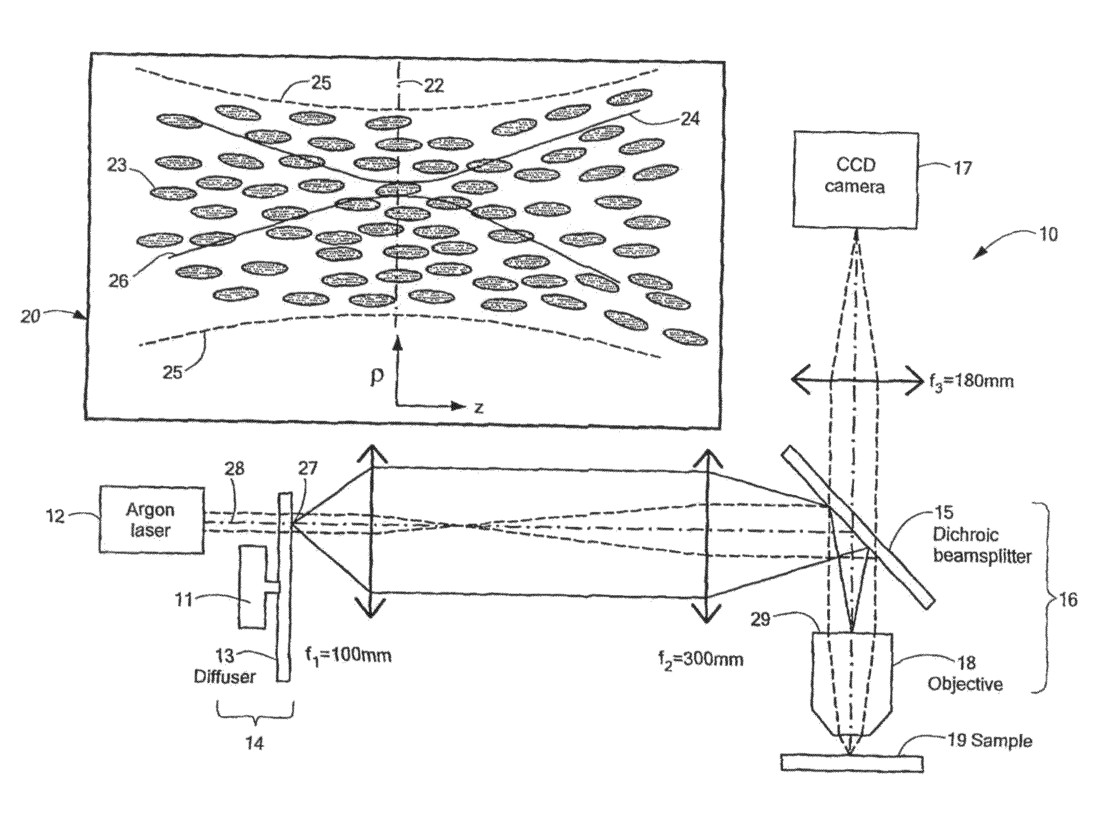
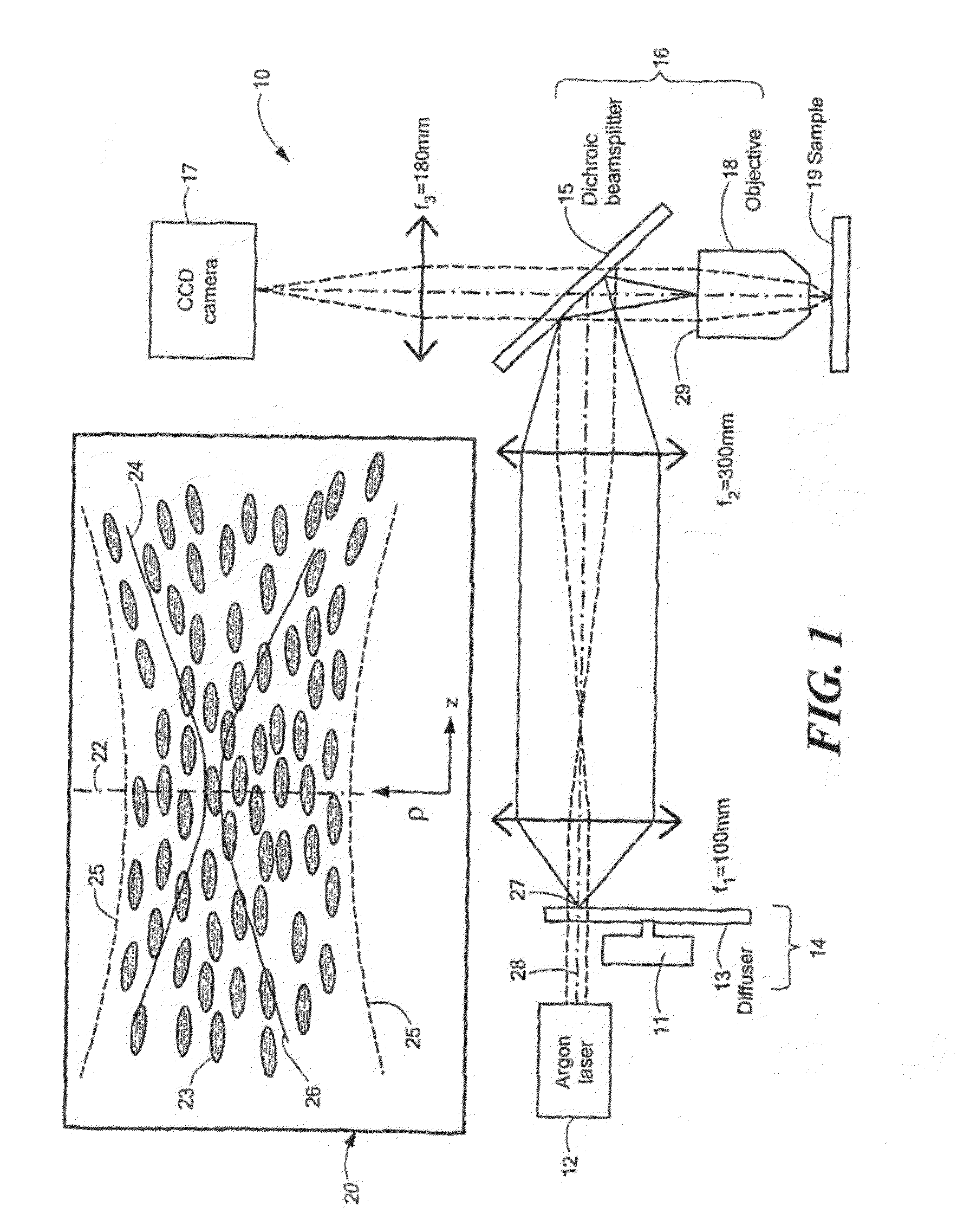
[0032]Microscopy by dynamic speckle illumination (DSI) and a system and method for performing the same are disclosed. DSI microscopy includes a modification to a standard wide-field fluorescence microscope. Advantageously, DSI microscopy provides depth discrimination in relatively thick tissues without the use of a complicated scanning mechanism.

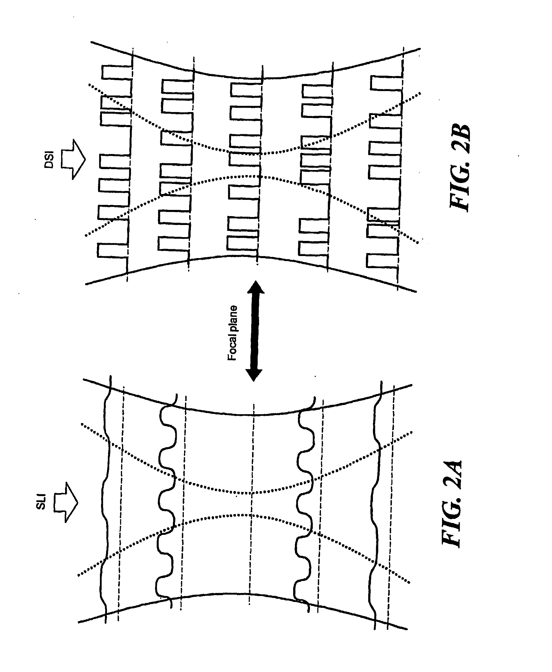
[0033]DSI microscopy is similar to SLI microscopy in some ways. However, in place of an incoherent grid pattern for illumination, DSI microscopy illuminates target objects using a coherent speckle pattern. The consequences of this seemingly innocuous replacement are quite significant.

[0034]Although the phenomenon of speckle is well known, its properties are often poorly understood. Speckle arises from the coherent superposition of light rays possessing random phases. For example, when a laser beam is reflected off a grainy surface, the variations in the surface relief provoke random phases throughout the beam profile, which in turn impart an...


PUM

PropertyMeasurementUnit
wavelength rangeaaaaaaaaaa
thicknessaaaaaaaaaa

Abstract

A versatile, imaging system that uses dynamic speckle illumination (DSI) is disclosed. The DSI microscope includes at least one light source for producing light to illuminate a target object in an object plane; an image recording device for recording a sequence of images of the target object; imaging optics for transmitting signal light from the target object as the sequence of images from the target object to the image recording device; and a dynamic speckle generating system for illuminating the target object with dynamic speckle.

Description

CROSS REFERENCE TO RELATED APPLICATIONS[0001]This application claims the benefit of U.S. provisional patent application No. 60 / 740,498 filed on Nov. 29, 2005 and U.S. provisional patent application No. 60 / 715,953 filed on Sep. 9, 2005, which are incorporated herein in their entirety by reference.STATEMENT REGARDING FEDERALLY SPONSORED RESEARCH OR DEVELOPMENT[0002]N / ABACKGROUND OF THE INVENTION[0003]The present invention discloses a system and a method of imaging and, more particularly, a system and method of fluorescence imaging using dynamic speckle illumination that suppresses out-of-focus background.[0004]By definition, optical, depth sectioning implies an ability to determine the axial position of a thin uniform plane. It is well known to those skilled in the relevant art that standard wide-field fluorescence microscopy cannot provide optical, depth sectioning. Indeed, with wide-field microscopy, a uniform fluorescent plane produces the same image independently of its axial posi...

Claims


Application Information

Patent Timeline
Patent Type & Authority Applications(United States)
IPC IPC(8): G01N21/64G01J1/58
CPCG02B21/0056G02B21/16G02B21/0076
Inventor MERTZ, JEROMEVENTALON, CATHERINE
Owner TRUSTEES OF BOSTON UNIV
Why Eureka
Try Eureka