Rotation detecting device and bearing assembly equipped with such rotation detecting device

a technology of rotating detecting device and bearing assembly, which is applied in the direction of mechanical equipment, instruments, transportation and packaging, etc., can solve the problems of inability to manufacture in compact size, inability to detect absolute angles with high precision, and complicated structure, etc., to achieve simple structure and high precision

Active Publication Date: 2010-09-09
NTN CORP
View PDF12 Cites 43 Cited by
  • Summary
  • Abstract
  • Description
  • Claims
  • Application Information

AI Technical Summary

Benefits of technology

[0014]An object of the present invention is to provide a rotation detecting device simple in structure and capable of detecting the absolute angle with high precision without being affec

Problems solved by technology

It has, however, been found that in the case of the rotation detecting device disclosed in the Patent Document 1 listed above, it is difficult to detect the absolute angle with the use of the magnetic encoder and to secure a rotation pulse of a high resolution.
Also, in the case of the rotation detecting device disclosed in the

Method used


Image

  • Rotation detecting device and bearing assembly equipped with such rotation detecting device
  • Rotation detecting device and bearing assembly equipped with such rotation detecting device
  • Rotation detecting device and bearing assembly equipped with such rotation detecting device

Examples


Embodiment Construction

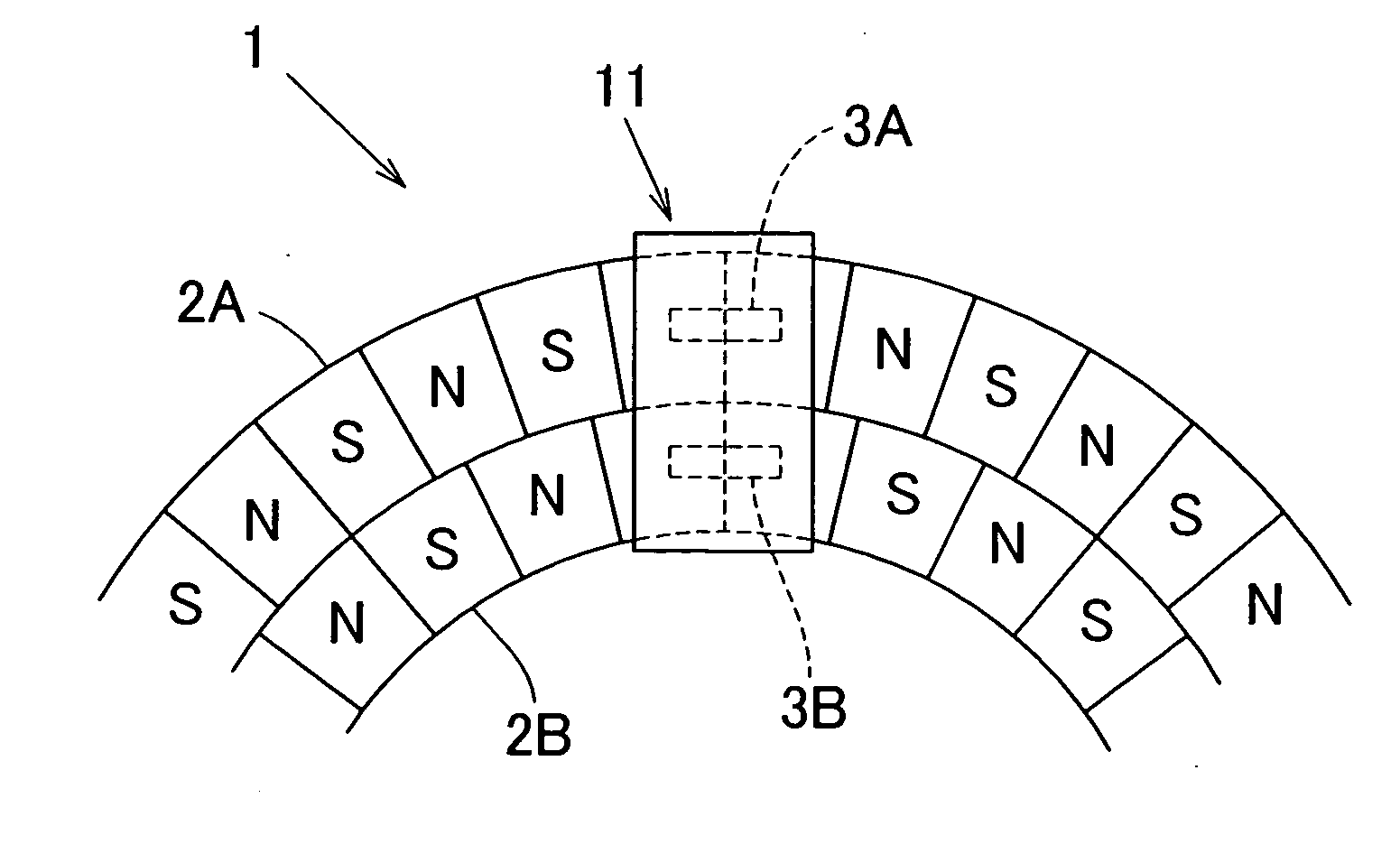
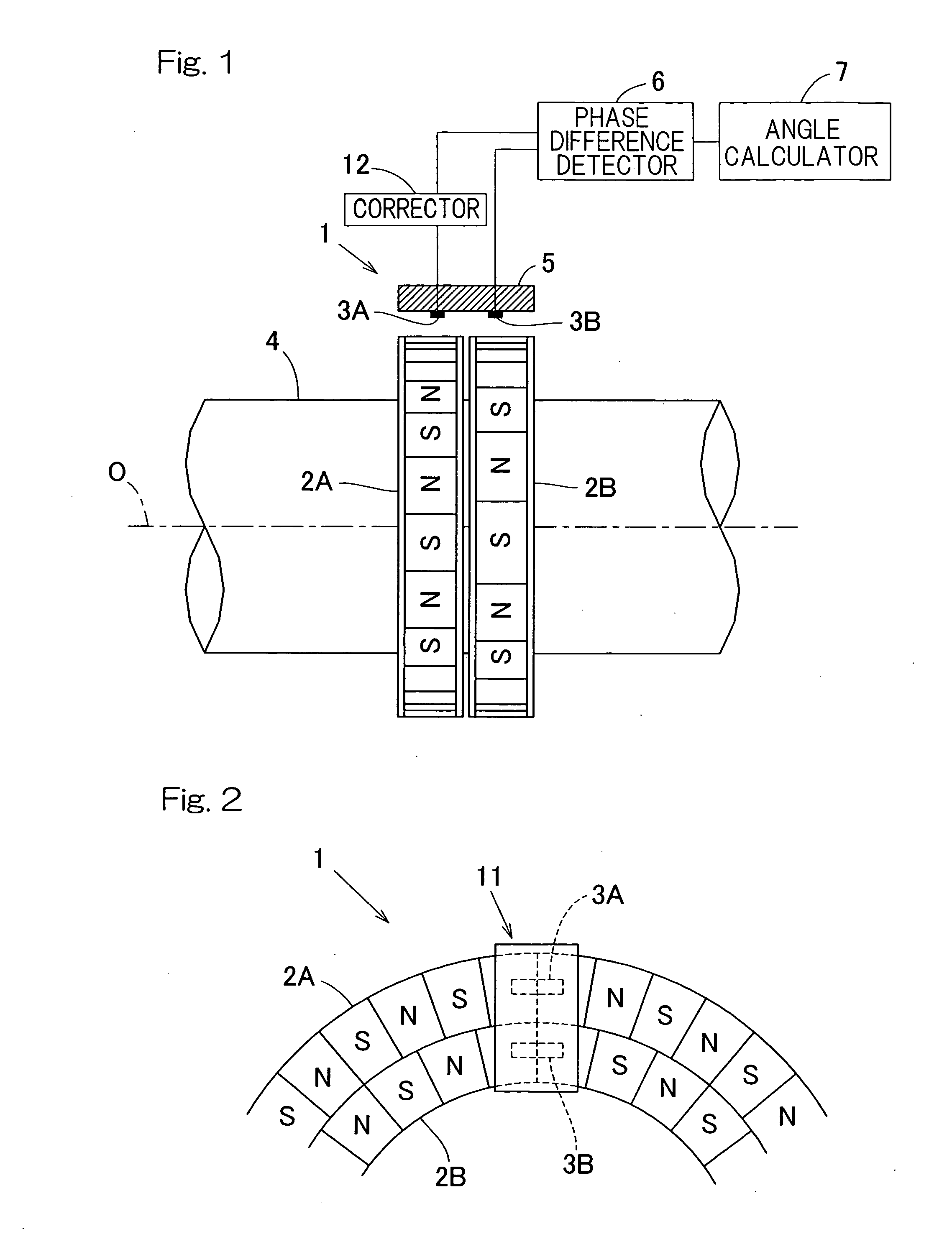
[0044]A first preferred embodiment of the present invention will be described in detail with particular reference to FIGS. 1 to 10. FIG. 1 illustrates a schematic structure of a rotation detection device according to this embodiment. This rotation detection device 1 includes a plurality of (for example, two, in the illustrated embodiment) magnetic encoders 2A and 2B mounted on an outer periphery of a rotating member 4 such as, for example, a rotary shaft of a motor or a rotatable ring of a wheel support bearing assembly, each in a ring shape in coaxial relation with the longitudinal axis O of the rotating member 4, and a plurality of (for example, two, in the illustrated embodiment) magnetic sensors 3A and 3B for detecting respective magnetic fields emanating from the associated magnetic encoders 2A and 2B. The magnetic sensors 3A and 3B are, in the illustrated embodiment, provided at a stationary member 5 such as, for example, a housing of the motor or a stationary ring of the bear...


PUM


Abstract

A rotation detecting device includes a plurality of magnetic encoders disposed coaxially and having respective numbers of magnetic poles different from each other and a plurality of magnetic sensors for detecting respective magnetic fields emanating from those magnetic encoders. Each of the magnetic sensors is in a ring form and obtains the position information within the magnetic poles of the associated magnetic encoder. A phase difference detector determines the difference in phase between magnetic field signals detected respectively by the magnetic sensors. An angle calculator is provided, which is operable on the basis of the difference in phase so detected to calculate an absolute angle of each of the magnetic encoders. A corrector corrects the initial phase difference occurring in the magnetic field signals, detected respectively by the magnetic sensors, as a result of the fitting position of the magnetic encoders.

Description

[0001]CROSS REFERENCE TO THE RELATED APPLICATION[0002]This application is based on and claims the Convention priority to Japanese patent application No. 2007-250443, filed Sep. 27, 2007, the entire disclosure of which is herein incorporated by reference as a part of this application.FIELD OF THE INVENTION[0003]The present invention relates to a rotation detecting device that is used in various machines and equipments for detecting the angle of rotation, and in particular for detecting the angle of rotation for the purpose of controlling the rotation of various motors, and also to a rotation detector equipped bearing assembly having such rotation detection device mounted thereon.BACKGROUND ART[0004]A rotation detection device of this kind has been suggested, which includes a ring-shaped magnetic pulse generating means such as, for example, a magnetic encoder having magnetic pole pairs in a direction circumferentially thereof and for generating magnetic pulses, and a plurality of dete...

Claims


Application Information

Patent Timeline
IPC IPC(8): G01B7/30
CPCF16C2326/02G01D5/145G01D5/2448F16C41/007G01P3/443G01P3/487G01D5/2452G01D5/2449G01D2205/80
Inventor TAKAHASHI, TORUUENO, SHINTAROUDESBIOLLES, PASCAL
Owner NTN CORP
Why Eureka
Try Eureka