Developing device and image forming apparatus using the same

a technology of developing device and image forming apparatus, which is applied in the direction of electrographic process apparatus, instruments, optics, etc., can solve the problems of uneven toner concentration and lower agitation performance of developers, and achieve the reduction of developer conveying performance, enhance developer conveying speed, and improve developer agitation performance.

Active Publication Date: 2010-09-09
SHARP KK
View PDF7 Cites 8 Cited by
  • Summary
  • Abstract
  • Description
  • Claims
  • Application Information

AI Technical Summary

Benefits of technology

[0023]According to the developing device of the fourth aspect of the present invention, it is possible to improve agitation performance (agitation effect) of the developer between the interior wall of the developer conveying passage and the developer conveying member without a noticeable reduction of developer conveying performance.
[0024]Here, if the helical angle is less than 60°, the rotational component of the force from the outer helical blade acting on the developer becomes relatively greater, hence the friction between the developer conveyed by the outer helical blade and the interior wall of the developer conveying passage becomes large. As a result, the developer is prone to clump and stick to the interior wall of the developer conveying passage. In contrast, if the helical angle exceeds 80°, the developer readily moves in the outward (radial) directions of the developer conveying member, so that the developer conveying speed along the axial direction of the developer conveying member becomes lower. As a result, it is necessary to raise the rotational speed of the developer conveying member in order to enhance the developer conveying speed, hence the developer is prone to clump and stick to the interior wall of the developer conveying passage due to frictional heat generated between the developer and the developer conveying member.
[0025]According to the developing device of the fifth aspect of the present invention, since the outer helical blade operates so as to push back the developer with respect to the developer conveying direction of the inner helical blade, it is possible to further improve agitation of the developer in the space between the interior wall of the developer conveying passage and the developer conveying member.
[0026]According to the sixth aspect of the present invention, since the flow of the developer near the interior wall of the developer conveying passage for developer conveyance is made to vary in speed if the rotational rate of the developer conveying member in the developing device is increased, it is possible to prevent the developer from stagnating around the interior wall of the developer conveying passage and hence inhibit toner concentration unevenness. As result, it is possible to produce images free from density unevenness.

Problems solved by technology

However, this configuration has suffered the problem that if the rotational speed of the augers is increased in order to raise the speed of developer conveyance, the developer near the interior wall of the developer conveying passage (the space between the auger screw and the wall) is left behind from the developer that is conveyed by the auger screw, stagnating therein.
As a result, the developer's agitation performance lowers, causing the problem of toner concentration unevenness.

Method used


Image

  • Developing device and image forming apparatus using the same
  • Developing device and image forming apparatus using the same
  • Developing device and image forming apparatus using the same

Examples


first embodiment

The First Embodiment

[0036]Now, the embodied modes for carrying out the present invention will be described with reference to the drawings.

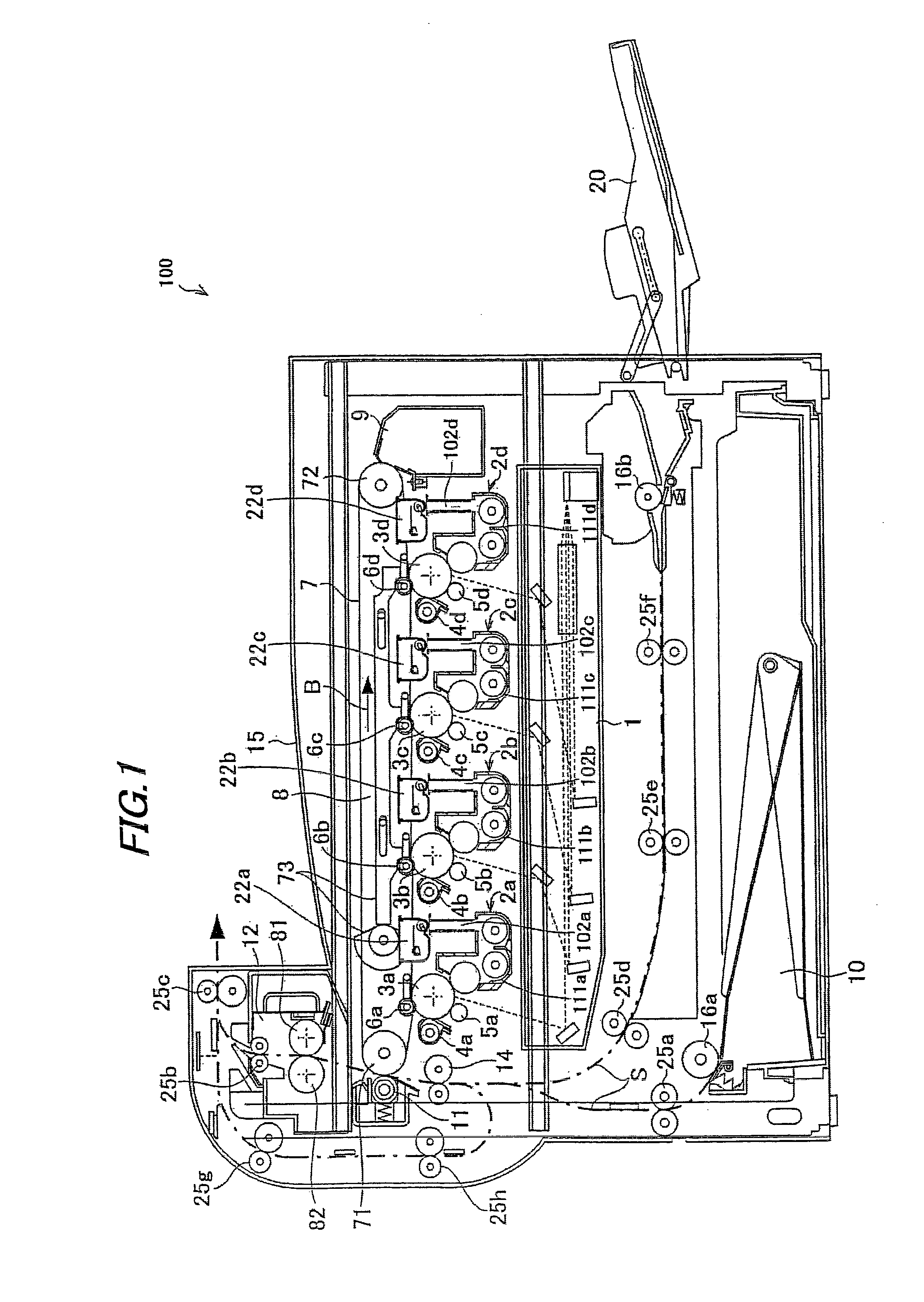
[0037]FIG. 1 shows one exemplary embodiment of the present invention, and is an illustrative view showing the overall configuration of an image forming apparatus including a developing device according to the first embodiment of the present invention.

[0038]An image forming apparatus 100 of the present embodiment forms an image with toners based on electrophotography, including: as shown in FIG. 1, photoreceptor drums 3a, 3b, 3c and 3d (which may be also called “photoreceptor drums 3” when general mention is made) for forming electrostatic latent images on the surfaces thereof; chargers (charging devices) 5a, 5b, 5c and 5d (which may be also called “chargers 5” when general mention is made) for charging the surfaces of photoreceptor drums 3; an exposure unit (exposure device) 1 for forming electrostatic latent images on the photoreceptor drum 3 sur...

second embodiment

The Second Embodiment

[0144]Next, the second embodiment for carrying out the present invention will be described with reference to the drawings.

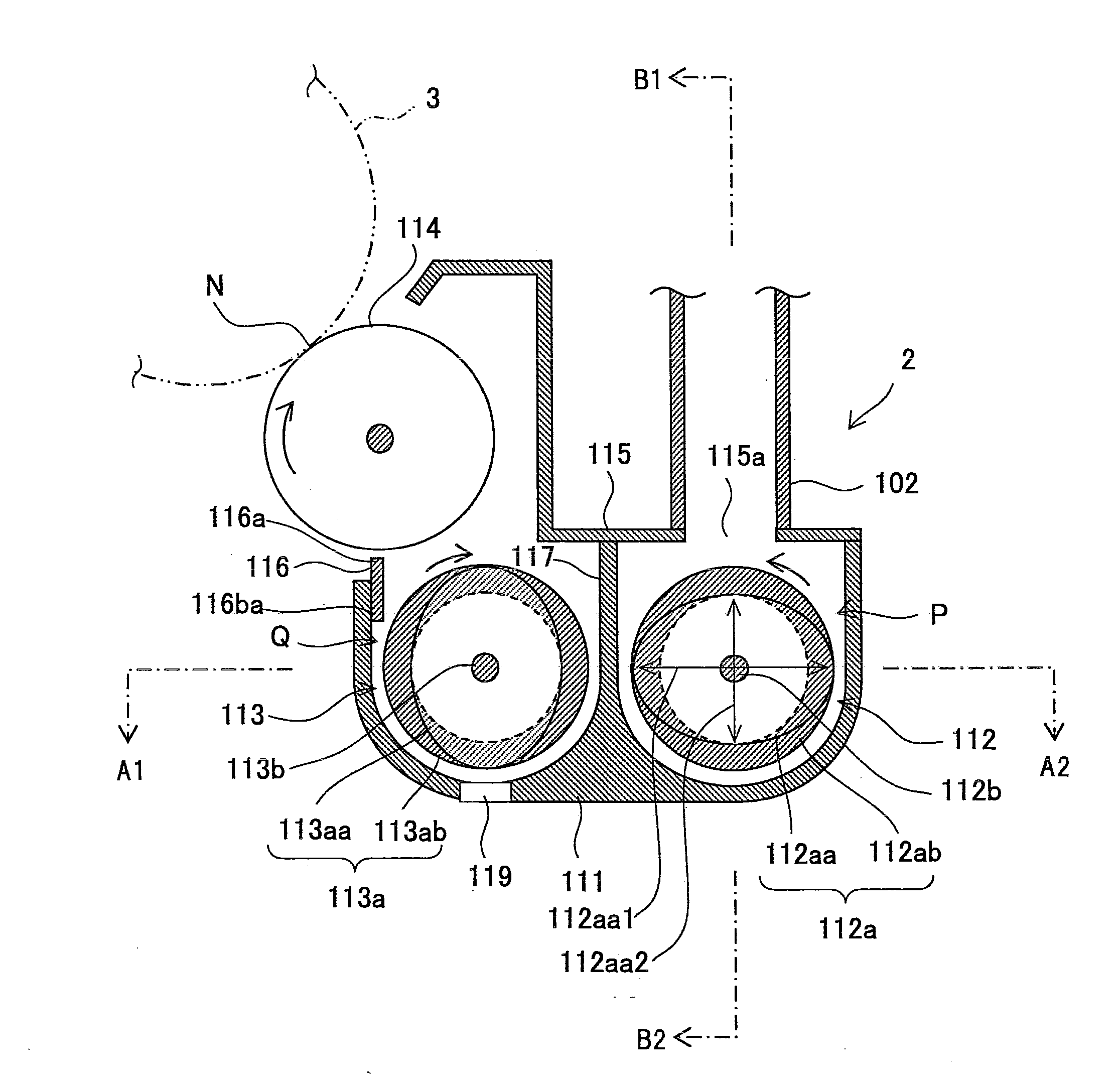
[0145]FIG. 8 is a sectional view showing the configuration of a developing device according to the second embodiment of the present invention. FIG. 9 is a sectional view cut along a plane D1-D2 in FIG. 8, showing a first conveying member as a part of the developing device.

[0146]Since the developing device of the second embodiment has the same configuration as that of developing device 2 of the first embodiment except in that the outer helical blade as a part of the first conveying member has opposite helical direction (that conveys the developer in the opposite direction) to that of the inner helical blade, the components having the same configurations will be allotted with the same reference numerals and description on those is omitted.

[0147]As shown in FIG. 8, a developing device 202 according to the second embodiment is constructed such th...


PUM


Abstract

A developing device includes a developing vessel for storing a developer, a first conveying passage, a second conveying passage, a first conveying member and a second conveying member to supply toner to a photoreceptor drum. The first conveying member includes a first rotary shaft and a first multi-helically structured blade. The first multi-helically structured blade includes a first inner helical blade and ring-shaped first outer helical blade. The first inner helical blade is formed so that the radius of the helical blade varies cyclically. The second helical pitch of the first outer helical blade is smaller than the first helical pitch of the first inner helical blade. The first outer helical blade inscribes the outer periphery of the first inner helical blade at its minimum radius portions.

Description

[0001]This Nonprovisional application claims priority under 35 U.S.C. §119 (a) on Patent Application No. 2009-053530 filed in Japan on 6 Mar. 2009, the entire contents of which are hereby incorporated by reference.BACKGROUND OF THE INVENTION[0002](1) Field of the Invention[0003]The present invention relates to a developing device and an image forming apparatus using the device, in particular relating to a developing device using a dual-component developer containing a toner and a magnetic carrier, for use in an image forming apparatus for forming images using the toner based on electrophotography, such as an electrostatic copier, laser printer, facsimile machine or the like, as well as to an image forming apparatus using this device.[0004](2) Description of the Prior Art[0005]Conventionally, image forming apparatuses based on electrophotography such as copiers, printers, facsimile machines and the like have been known. The image forming apparatus using electrophotography is construc...

Claims


Application Information

Patent Timeline
Patent Type & Authority Applications(United States)
IPC IPC(8): G03G15/08
CPCG03G15/0875G03G15/0877G03G15/0893G03G15/0879
Inventor MIHARA, KOICHI
Owner SHARP KK
Why Eureka
Try Eureka