Bearingless motor

a bearingless motor and bearing technology, applied in the direction of engine components, mechanical energy handling, mechanical apparatus, etc., can solve the problems of difficult to generate suspension force, difficult to stably perform magnetic levitation and rotation, and difficult to generate sufficient radial suspension force with a normal consequent-pole type structur

Inactive Publication Date: 2010-09-16
TOKYO UNIV OF SCI EDUCATIONAL FOUND
View PDF6 Cites 46 Cited by
  • Summary
  • Abstract
  • Description
  • Claims
  • Application Information

AI Technical Summary

Benefits of technology

[0064]As explained above, according to the present invention, the thrust magnetic bearing unit including the stator having the thrust suspension winding wound around the rotor shaft and the rotor part facing this stator with a predetermined gap therebetween is arranged between the first bearingless mot...

Problems solved by technology

The wide gap length increases magnetic resistance and makes it difficult to generate suspension force for suspending the rotor, which makes it difficult to stably perform magnetic levitation and...

Method used


Image

  • Bearingless motor
  • Bearingless motor
  • Bearingless motor

Examples


first embodiment

[0117]Hereinafter, embodiments of the present invention will be explained. First, the present invention proposes a new structure capable of performing 5-axis active control while forming the rotor into an entirely cylindrical shape by removing a thrust disk considered as one of the conventional structural problems.

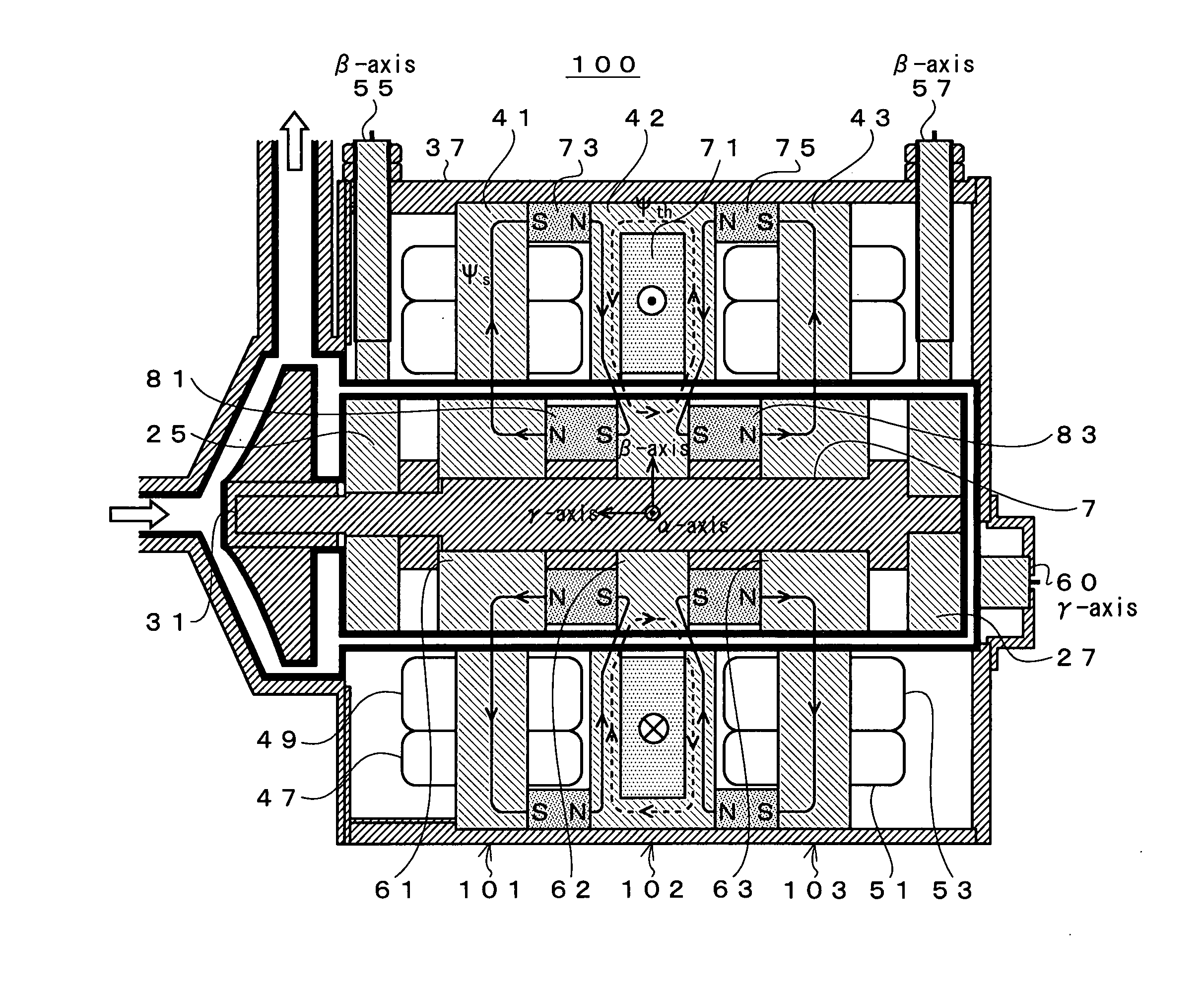
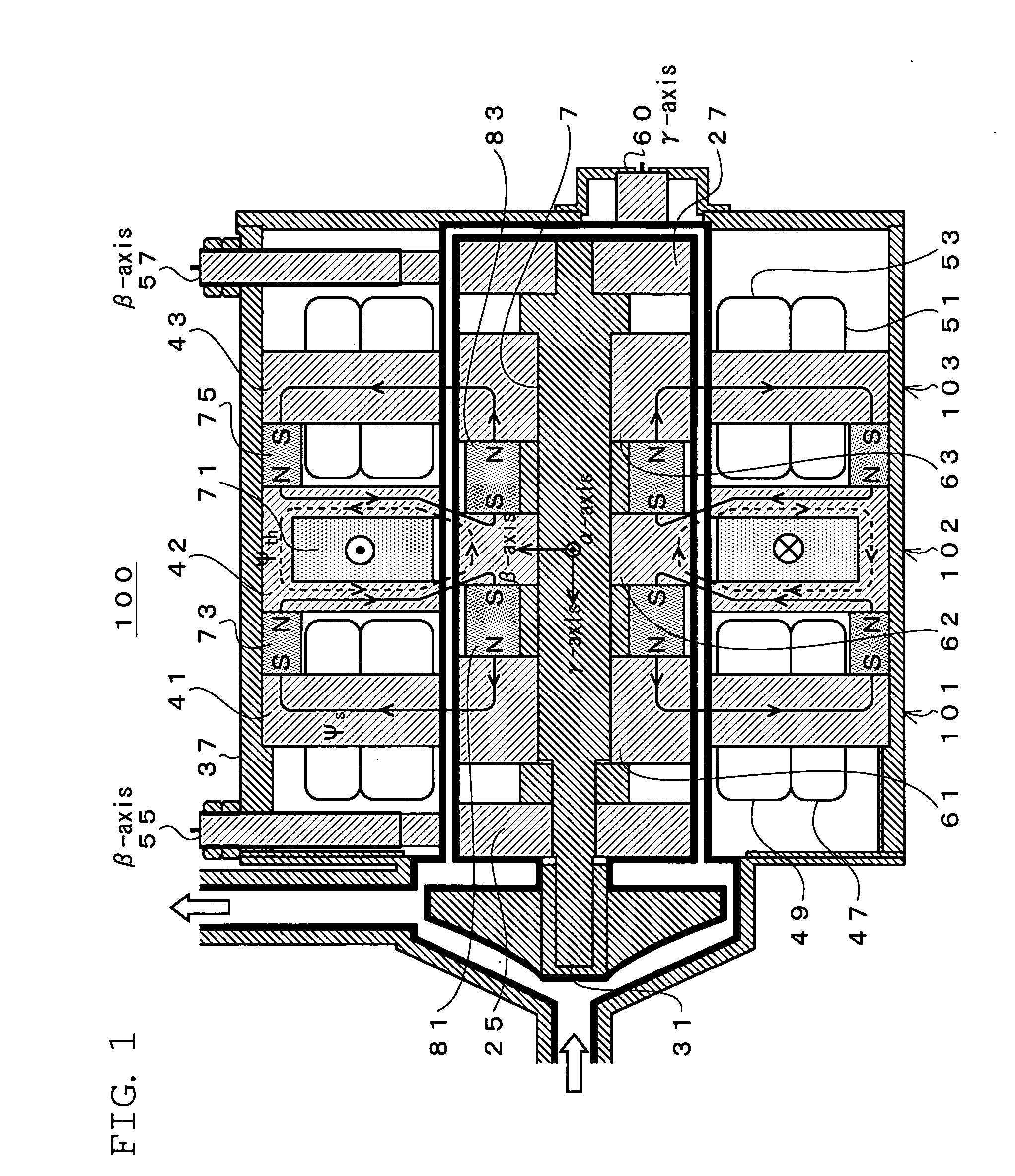
[0118]FIG. 1 shows a block diagram of the first embodiment of the present invention. Note that the same components as those in FIG. 18 are given the same symbols, and the explanation thereof will be omitted.

[0119]In FIG. 1, a 5-axis active control type bearingless motor 100 excluding a thrust disk has rotor cores divided into three blocks. Specifically, a first bearingless motor unit 101 is formed of the stator 41 and a core 61 arranged to face each other, while a second bearingless motor unit 103 is formed of the stator 43 and a core 63.

[0120]A thrust magnetic bearing unit 102 formed of a core 62 and a stator 42 while having the functions of a thrust magnetic bearing is n...

second embodiment

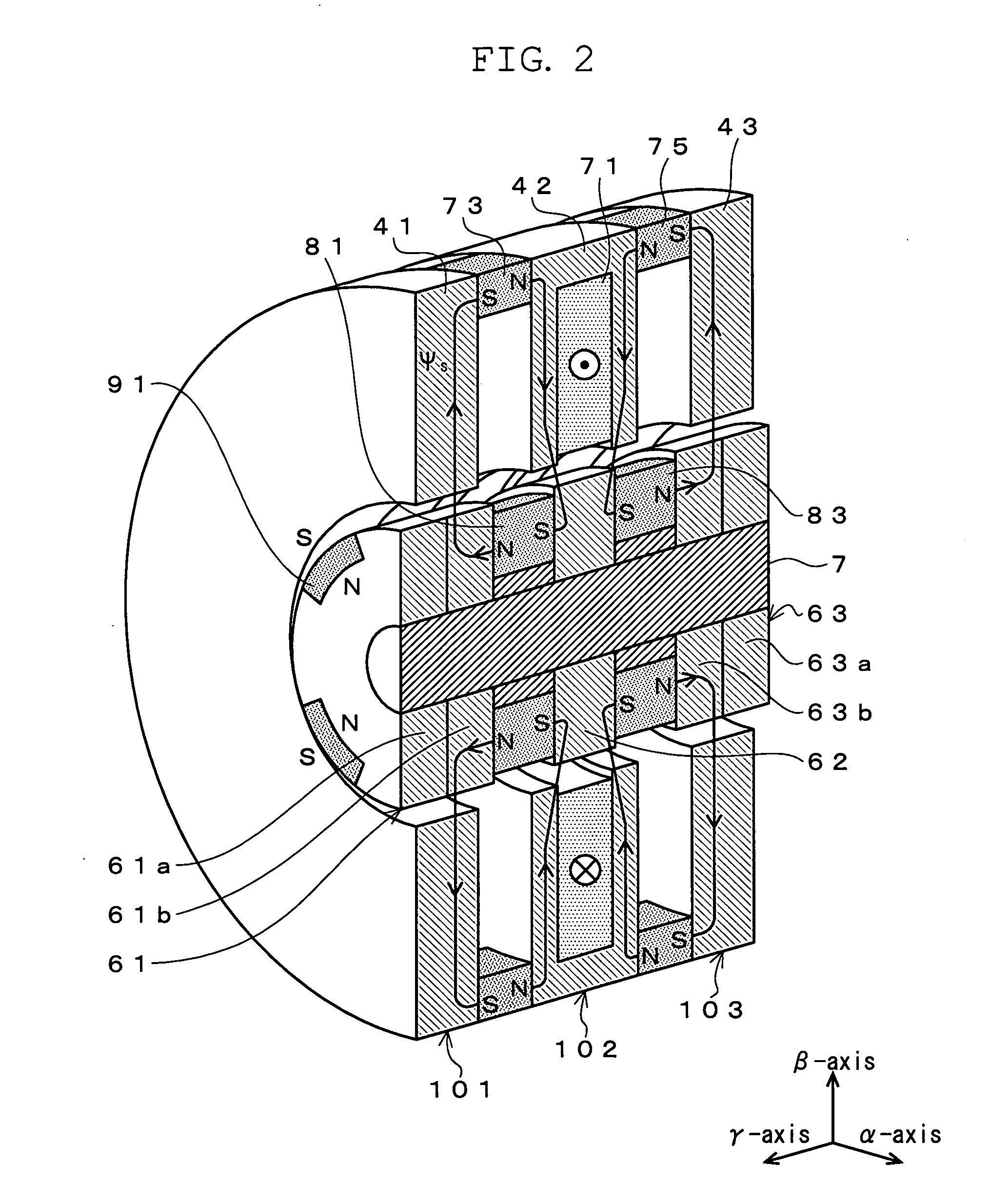
[0150]Each of FIG. 10 and FIG. 11 shows a principle of how the radial suspension force is generated in the 5-axis active control type bearingless motor according to the present invention. As shown in FIG. 10, in the gap around the radial permanent magnets (corresponding to the axial left half 61a of the unit 101 and the axial right half 63a of the unit 103), the magnetic flux in the upper position and that in the lower position always flow in the same direction, by which the density of the magnetic flux in the upper gap does not differ from that in the lower gap even when the radial suspension magnetic flux ψs2β is generated and thus the radial suspension force is not generated.

[0151]On the other hand, as shown in FIG. 11, in the cylindrical portion of the rotor (corresponding to the axial right half 61b of the unit 101 and the axial left half 63b of the unit 103), the bias magnetic flux radially flows from the rotor center, and thus the radial suspension magnetic flux is generated ...


PUM


Abstract

Provided is a bearingless motor capable of stably performing magnetic levitation and rotation even when a thrust disk is not provided and gap length is wide.
A unit 101 of a first bearingless motor is formed of a stator 41 and a core 61, while a unit 103 of a second bearingless motor is formed of a stator 43 and a core 63. A thrust magnetic bearing unit 102 formed of a core 62 and a stator 42 while having the functions of a thrust magnetic bearing is newly arranged between the unit 101 and the unit 103. A stator-side annular thrust permanent magnet 73 and a rotor-side annular thrust permanent magnet 81 are arranged between the unit 101 and the unit 103, while a stator-side annular thrust permanent magnet 75 and a rotor-side annular thrust permanent magnet 83 are arranged between the unit 102 and the unit 103.

Description

TECHNICAL FIELD [0001]The present invention relates to a bearingless motor, and particularly relates to a bearingless motor capable of stably performing magnetic levitation and rotation even when a thrust disk is not provided and gap length is wide.BACKGROUND ART [0002]A bearingless motor has been energetically studied and developed inside and outside the country in order to realize a high-speed, high-power, and maintenance-free motor (see Non-patent. Documents 1 to 5). The bearingless motor is an electric rotating machine formed by combining a motor and a magnetic bearing by arranging two kinds of windings, namely motor winding and suspension windings, around one stator, thereby the motor itself having the functions of the magnetic bearing. Since the rotor can be magnetically suspended in a noncontact manner, the bearingless motor does not cause friction or dust and does not require lubrication, which eliminates the need for periodic maintenance.[0003]When such a bearingless motor ...

Claims


Application Information

Patent Timeline
IPC IPC(8): H02K7/09
CPCF16C32/0459F16C2360/44H02K7/09F16C32/0493
Inventor CHIBA, AKIRATAKEMOTO, MASATSUGUFUKAO, TADASHI
Owner TOKYO UNIV OF SCI EDUCATIONAL FOUND
Why Eureka
Try Eureka