Charging system for electric vehicle

a charging system and electric vehicle technology, applied in the direction of charging stations, battery/cell propulsion, transportation and packaging, etc., can solve the problems of limited resources of electric vehicles, environmental pollution, and huge public expenses for enhancing the capacity of electric generation and electric transmission systems

Inactive Publication Date: 2010-09-16
LS IND SYETEMS CO LTD
View PDF10 Cites 19 Cited by
  • Summary
  • Abstract
  • Description
  • Claims
  • Application Information

AI Technical Summary

Benefits of technology

[0007]A typical electric supplying system being presented is optimized for using domestic electric appliances or operating machineries in factories. If an electric vehicle is supplied of energy from the typical electric supplying system, not only its capacity of electric generation but also infrastructure for electric transmission system must be expanded. Enhancing the capacity of electric generation and the electric transmission system require huge public expenses.

Problems solved by technology

However, those vehicles must use limited resources, i.e., oil.
A problem of an environmental pollution occurs in the process of consuming the oil.
Enhancing the capacity of electric generation and the electric transmission system require huge public expenses.

Method used


Image

  • Charging system for electric vehicle
  • Charging system for electric vehicle
  • Charging system for electric vehicle

Examples


Embodiment Construction

[0018]Exemplary implementations of the present disclosure will be described with reference to the accompanying drawings.

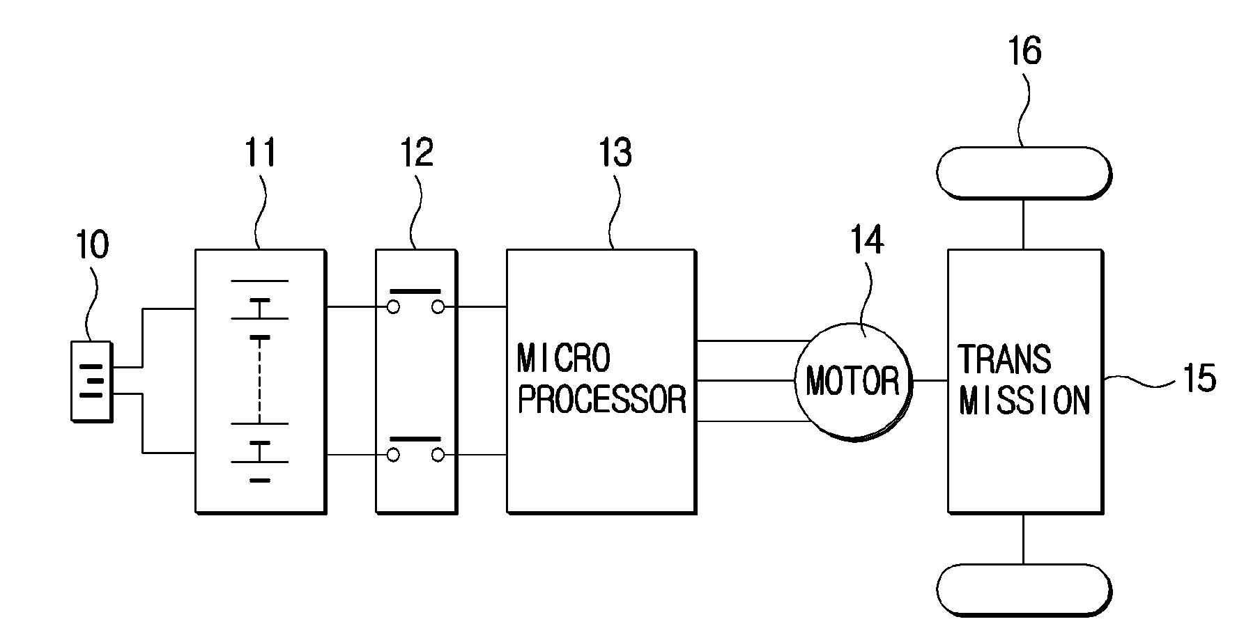
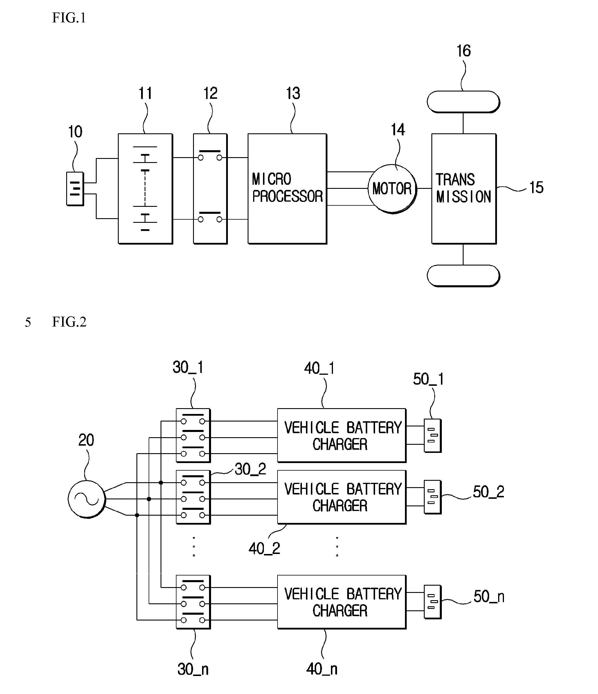
[0019]FIG. 1 is a block diagram of an electric vehicle.

[0020]As shown, the electric vehicle includes a charging terminal 10, a vehicle battery 11, a power relay assembly unit 12, a microprocessor 13, a motor 14, a transmission 15, and tires 16. The charging terminal 10 is a terminal for receiving an electric signal. The electric signal supplied through the charging terminal 10 is stored by the vehicle battery 11. The electric signal stored in the vehicle battery 11 is inputted to the microprocessor 13 through the power relay assembly unit 12. The microprocessor 13 controls a torque and an operation speed of the motor 14. The transmission 15 operates the motor 14 with the electric signal stored in the vehicle battery 11. Mechanical force transferred through the transmission that is mechanically connected to the motor 14 rotates the tires 16.

[0021]FIG. 2 illustrates ...


PUM


Abstract

An electric vehicle charging system is disclosed, wherein the electric vehicle charging system comprises: a station battery bank storing electric energy; a station battery charging unit changing an AC signal to a DC signal that is supplied for the station battery bank; and a vehicle charging unit charging an electric vehicle with the DC signal from the station battery bank.

Description

CROSS-REFERENCE TO RELATED APPLICATIONS[0001]The present invention claims priority of Korean patent application number 10-2009-0020471, filed on Mar. 10, 2009, which are incorporated by reference in its entirety.BACKGROUND OF THE INVENTION[0002]1. Field of the Invention[0003]The present invention relates to a charging system and particularly, to an electric vehicle charging system.[0004]2. Description of the Related Art[0005]The invention of vehicles such as a car, a truck and a bus has contributed much to betterment of human life. However, those vehicles must use limited resources, i.e., oil. A problem of an environmental pollution occurs in the process of consuming the oil. An electric car that uses electric energy as a fuel has been developed to solve problems about exhaustion of resources, e.g., exhaustion of oil on earth and to develop environment friendly technology.[0006]Today, the electric vehicle technology includes a battery powered electric vehicle, a hybrid electric vehi...

Claims


Application Information

Patent Timeline
Patent Type & Authority Applications(United States)
IPC IPC(8): H02J7/00
CPCB60L11/1816Y02T10/7005Y02T90/14B60L2240/529B60L11/1805B60L11/1824B60L2210/30B60L2230/30B60L50/52B60L53/53Y02T10/70Y02T10/7072Y02T10/72Y02T90/12H02J7/14
Inventor YANG, CHUN SUK
Owner LS IND SYETEMS CO LTD
Why Eureka
Try Eureka