Capacitance measurement system and method

a capacitance measurement and capacitance measurement technology, applied in the field of circuits and techniques for measuring capacitance, can solve the problems of inconvenient capacitance measurement times for users, system is quite susceptible to noise, and the time required for capacitance measurement is time. to achieve the effect of improving the sensitivity of measuring

Active Publication Date: 2010-09-16
TEXAS INSTR INC
View PDF7 Cites 40 Cited by
  • Summary
  • Abstract
  • Description
  • Claims
  • Application Information

AI Technical Summary

Benefits of technology

[0027]In one embodiment, the method includes coupling a pump capacitor (CP) between the first terminals (21-0 . . . 21-k . . . 21-n) of the CDAC capacitors (25-0 . . . 25-k . . . 25-n) and a predetermined low reference voltage (GND) during the precharge phase and coupling the pump capacitor (CP) between the first terminals (21-0 . . . 21-k . . . 21-n) of the CDAC capacitors (25-0 . . . 25-k . . . 25-n) and a predetermined high reference voltage (VDD) during the measurement phase to boost the voltage of the first terminals (21-0 . . . 21-k . . . 21-n) of the CDAC capacitors (25-0 . . . 25-k . . . 25-n) to improve the sensitivity of the measuring with respect to relatively high values of the capacitance (CSENj) of the first capacitor (CSENj).

Problems solved by technology

A problem of the above described prior art is that the time required for the capacitance measurement is time-varying in the sense that a lower value of the capacitance CSENj requires less counting time by timer capture register 7, whereas a higher value of the capacitance CSENj requires more counting time by timer capture register 7.
The widely variable capacitance measurement times may be inconvenient for a user.
Also, the system is quite susceptible to noise because comparator 6 in Prior Art FIG. 1B is connected via CSAMPLE during the entire capacitance measurement process.

Method used


Image

  • Capacitance measurement system and method
  • Capacitance measurement system and method
  • Capacitance measurement system and method

Examples


Embodiment Construction

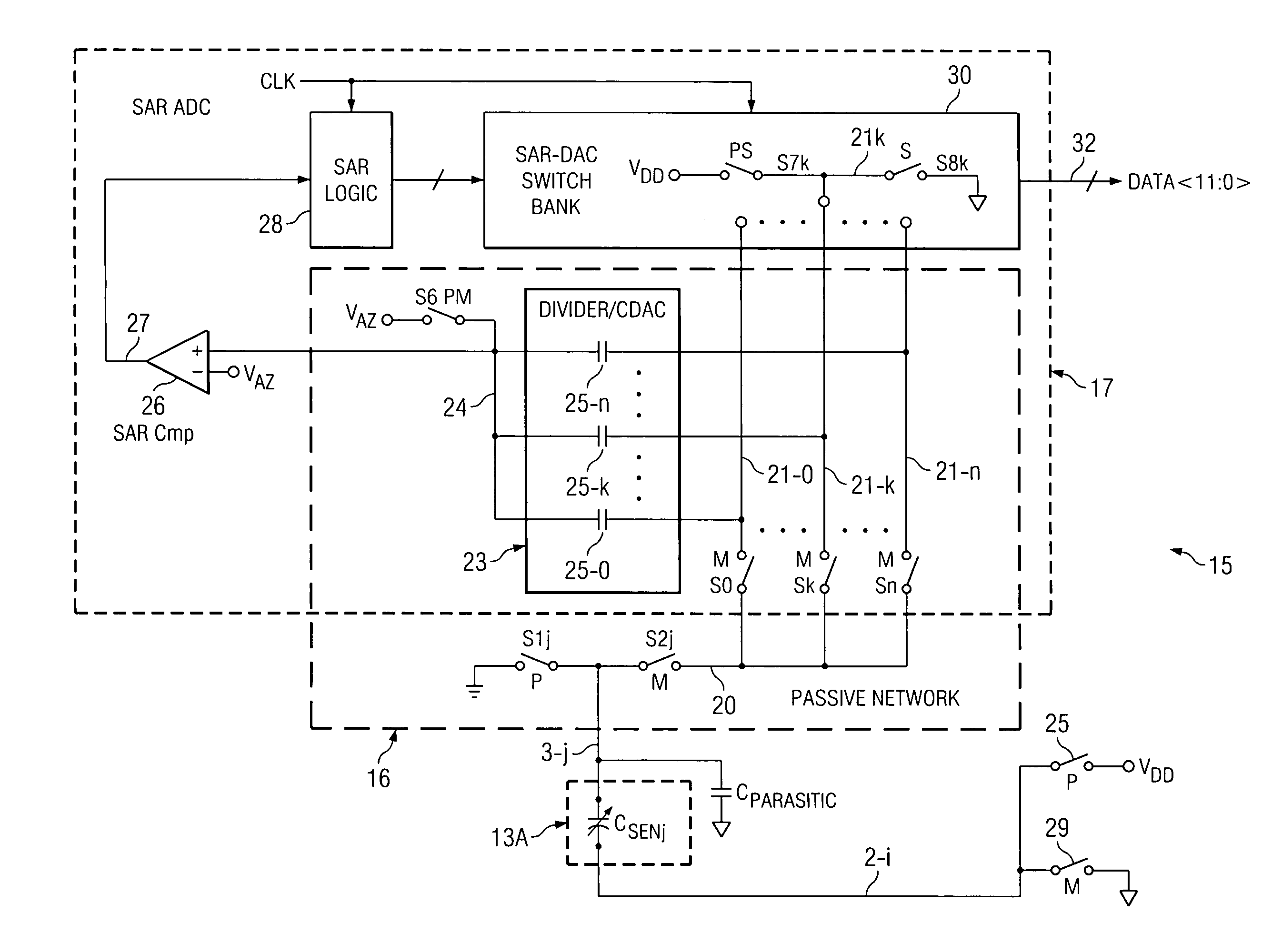
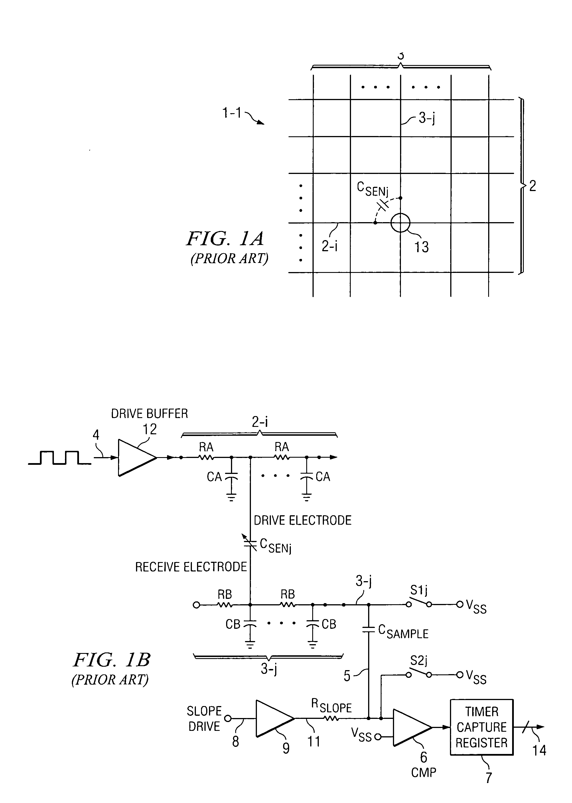
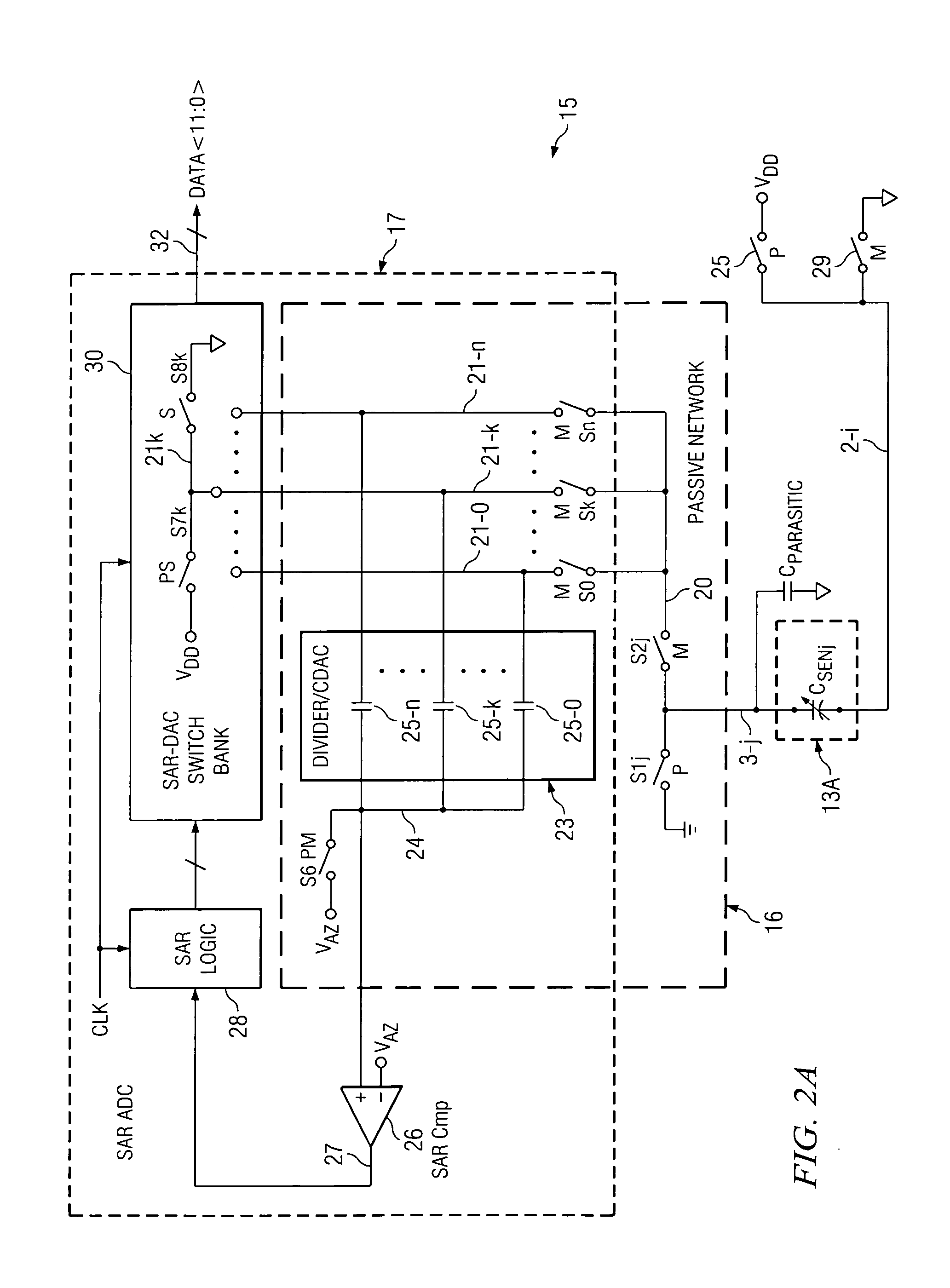
[0041]FIG. 2A shows a single-ended (i.e., not differential) embodiment of an embedded SAR based passive capacitance measurement system 15 of the present invention. Capacitance measurement system 15 includes a passive network 16 and a SAR (successive approximation register) type of ADC (analog-to-digital converter) 17. Passive network 16 is coupled by conductor 3-j to a touch screen capacitance CSENj. CSENj can be the same as a cross-coupling capacitance of an external touchscreen panel 13A as shown in Prior Art FIGS. 1A and 1B. (Alternatively, the capacitance CSENj can be a capacitance CSEN or CBUTTON of a touch button with one terminal connected to ground as shown in subsequently described FIG. 2F, rather than a touchscreen panel 13A as shown in FIG. 2A.) The capacitance CSENj (or CSEN) is decreased by the presence of a human finger or the like in the electric field associated with that capacitance.

[0042]In FIG. 2A, the lower left corner shows an external touch screen panel 13A. On...


PUM


Abstract

A capacitance measurement system precharges first terminals (21-0 . . . 21-k . . . 21-n) of a plurality of capacitors (25-0 . . . 25-k . . . 25), respectively, of a CDAC (capacitor digital-to-analog converter) (23) included in a SAR (successive approximation register) converter (17) to a first voltage (VDD) and pre-charges a first terminal (3-j) of a capacitor (CSENj) to a second voltage (GND). The first terminals are coupled to the first terminal of the capacitor to redistribute charges therebetween so as to generate a first voltage on the first terminals and the first terminal of the capacitor, the first voltage being representative of a capacitance of the first capacitor (CSENj). A SAR converter converts the first voltage to a digital representation (DATA) of the capacitor. The capacitance can be a touch screen capacitance.

Description

BACKGROUND OF THE INVENTION[0001]The present invention relates generally to circuits and techniques for measurement of capacitance, and more particularly to such circuits and techniques adapted for use in touch-screen applications, touch-pad applications, and the like.[0002]Touch screen controller circuits for use in touch screen, touch pad, and touch button applications have generally included digital controller circuitry and analog circuitry for detecting the presence of capacitance if a user touches a point on a touch screen (or a touch pad or touch button). The presence or movement of a user's finger in the vicinity of the electric field associated with the capacitance of the touch screen, touch button, etc., disturbs or impedes the electric field and therefore modifies the capacitance. The capacitance measurement circuit therefore indicates the presence of the finger as a change in the modified touchscreen or touch button capacitance. The prior art typically utilizes current so...

Claims


Application Information

Patent Timeline
Patent Type & Authority Applications(United States)
IPC IPC(8): G01R27/26
CPCG01D1/00G01D15/00G01R27/2605G06F3/044G01D21/00G06F3/0446
Inventor MUECK, MICHAELCORMIER, JR., RONALD F.
Owner TEXAS INSTR INC
Why Eureka
Try Eureka