RFID power control and monitoring system

a technology of power control and monitoring system, applied in the field of radiofrequency identification, can solve the problem of reducing the power required by the active rfid circuit, and achieve the effect of reducing the power required

Inactive Publication Date: 2010-09-16
NEW JERSEY MICROSYST
View PDF3 Cites 133 Cited by
  • Summary
  • Abstract
  • Description
  • Claims
  • Application Information

AI Technical Summary

Benefits of technology

[0013]According to a first aspect of the present invention, a hybrid RFID tag is described. The hybrid RFID tag contains both an active RFID circuit and a passive RFID circuit. The Active RFID circuit is typically powered by an external source such as the AC power grid or a solar panel. If this power source becomes unavailable or is degraded, e.g., during a brown-out, the active RFID circuit enters a sleep mode, which reduces the...

Problems solved by technology

If this power source becomes unavailable or is degraded, e.g., during a brown-out, the acti...

Method used


Image

  • RFID power control and monitoring system
  • RFID power control and monitoring system
  • RFID power control and monitoring system

Examples


Embodiment Construction

[0021]Aspects of the invention are disclosed in the following description and related drawings directed to specific embodiments of the invention. Alternate embodiments may be devised without departing from the spirit or the scope of the invention. Additionally, well-known elements of exemplary embodiments of the invention will not be described in detail or will be omitted so as not to obscure the relevant details of the invention. Further, to facilitate an understanding of the description, discussion of several terms used herein follows.

[0022]The word “exemplary” is used herein to mean “serving as an example, instance, or illustration.” Any embodiment described herein as “exemplary” is not necessarily to be construed as preferred or advantageous over other embodiments. Likewise, the term “embodiments of the invention” does not require that all embodiments of the invention include the discussed feature, advantage, or mode of operation.

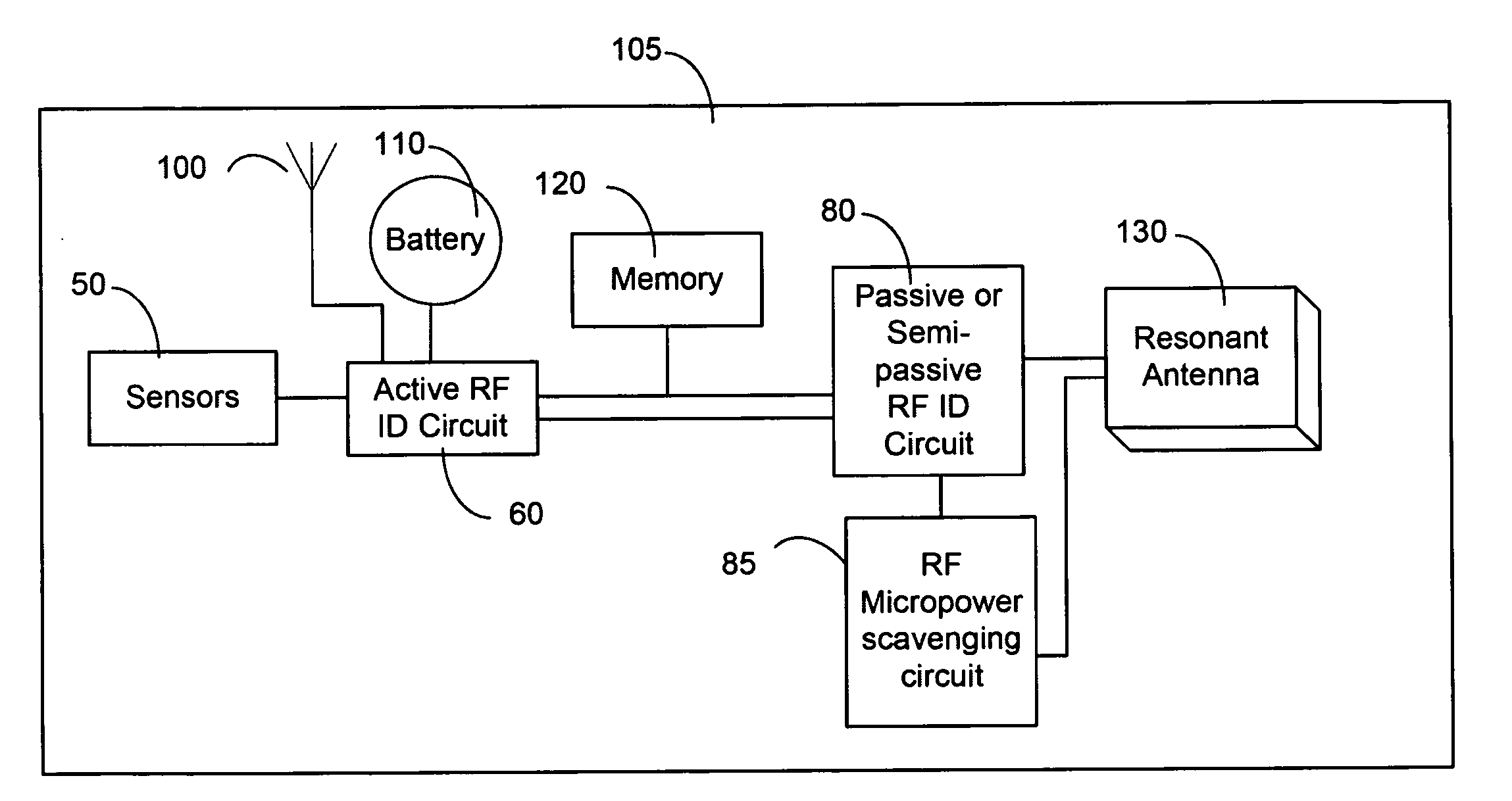
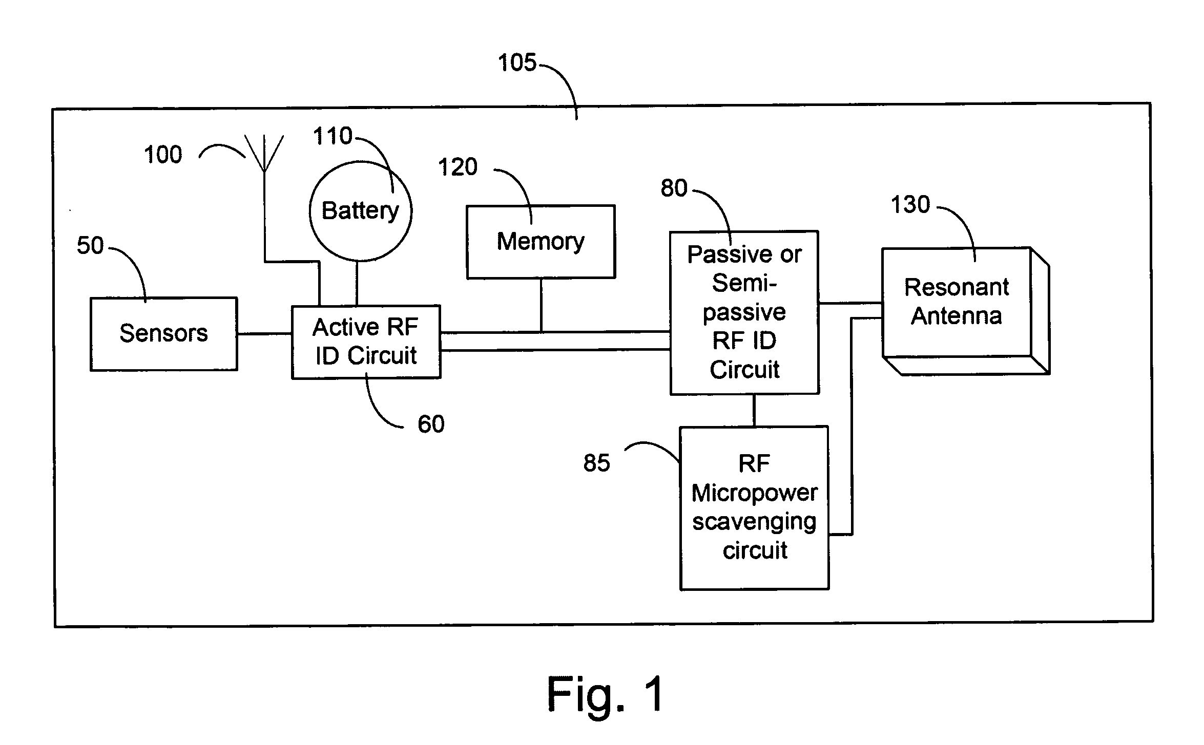
[0023]FIG. 1 is a schematic block diagram of a hy...


PUM


Abstract

A system for monitoring parameters associated with a device, such as current, voltage, power, temperature, energy consumed, moisture, fluid levels and flow, wind speed, identification parameters, and repair history. The system includes the use of hybrid RFID sensor tags including a combination of active, semi-passive, and passive RFID circuits. Hybrid tags are attached to electrical system components. Standalone electrical components and generators and those connected to the electrical grid may be monitored. Data collected and stored in the hybrid tags may be accessed via a wireless communication link between hybrid tags and either active scanners or a passive interrogators. The data collected and processed from the hybrid tags may be provided to a user via the Internet or another wired or wireless communication network.

Description

CROSS-REFERENCE TO RELATED APPLICATIONS[0001]The present application claims priority under 35 U.S.C. §119(e) from the following patent application which is incorporated herein by reference in its entirety: U.S. Provisional Patent Application Ser. No. 61 / 209,897, filed Mar. 13, 2009, entitled RFID Power Monitoring and Control System.BACKGROUND OF THE INVENTION[0002]1. Field of the Invention[0003]The present invention relates to Radio-frequency identification (RFID).[0004]2. Description of the Related Art[0005]RFID is the use of an object, which is typically referred to as an RFID tag, for the purpose of identification and tracking using radio waves. Generally, the RFID tag is physically attached to a product, person, or other object. RFID tags can be categorized into three basic types: active, passive, and semi-passive.[0006]An active RFID tag is a wireless device that is powered locally and contains a local radio frequency (RF) receiver and a source of RF power that actively transmi...

Claims


Application Information

Patent Timeline
IPC IPC(8): G06K7/00
CPCG06K19/0723H04Q9/00Y02B10/30H04Q2209/60H04Q2209/25H04Q2209/883H04Q2209/47
Inventor CARR, WILLIAM N.
Owner NEW JERSEY MICROSYST
Why Eureka
Try Eureka