
Traffic Monitoring

a technology for traffic monitoring and apparatus, applied in the field of traffic monitoring, can solve the problems of inaccurate measurement speed, time-consuming and costly installation, and the inability of traffic to use the road section, so as to reduce the frame rate and accuracy, and improve the accuracy

Inactive Publication Date: 2010-09-16
TRW LIMITED
View PDF15 Cites 15 Cited by
  • Summary
  • Abstract
  • Description
  • Claims
  • Application Information

AI Technical Summary

Benefits of technology

[0015]In one embodiment, the first and second lines may be visible features on the road surface; for example, they may be painted lines across the carriageway. However, this is not required, and the method may instead comprise the assignment of areas of road surface within the field of view of the camera as the first and second lines. Whilst physical lines on the surface of the carriageway are thought to be more accurate, the use of “virtual” lines assigned to the areas of carriageway but typically only existing within the apparatus carrying out the method requires less interference with the road.
[0052]The processing unit may comprise a temporal high pass filter, which acts on the captured images, such that only fast changes in the images are considered by the processing unit. This prevents longer-term trends, such as changes in ambient light due to the sun's movement across the sky or weather, affecting the detection of the visibility of the lines.

Problems solved by technology

Furthermore, it is not possible for traffic to use the section of road in which the coil in being installed during installation.
The installation is therefore often time consuming and costly.
Furthermore, carriageway works such as resurfacing tend to lead to destruction of the loops and so require reinstallation of the loops in the road surface.
When the use of two separate loops a known distance apart allows for the vehicle speed to be determined, if the performance of the two loops differs, then the difference in timing in threshold-crossing may lead to errors in measured speed.
Similarly, determining the length of a vehicle from the product of the vehicle speed and the length of time it is over one of the loops can be subject to the same errors.
Additionally, differences in detecting vehicles made of combinations of units, such as tractor units pulling trailers, may lead to further measurement errors.
Classifying vehicles using the output of inductive loops is also problematic.
Additionally, where pairs of inductive loops are employed in lanes, vehicles crossing lanes between the pairs of loops may not be detected correctly.
Also, inductive loops have difficulties operating correctly for vehicle speeds of over 100 km / h.

Method used


Image

  • Traffic Monitoring
  • Traffic Monitoring
  • Traffic Monitoring

Examples


Embodiment Construction

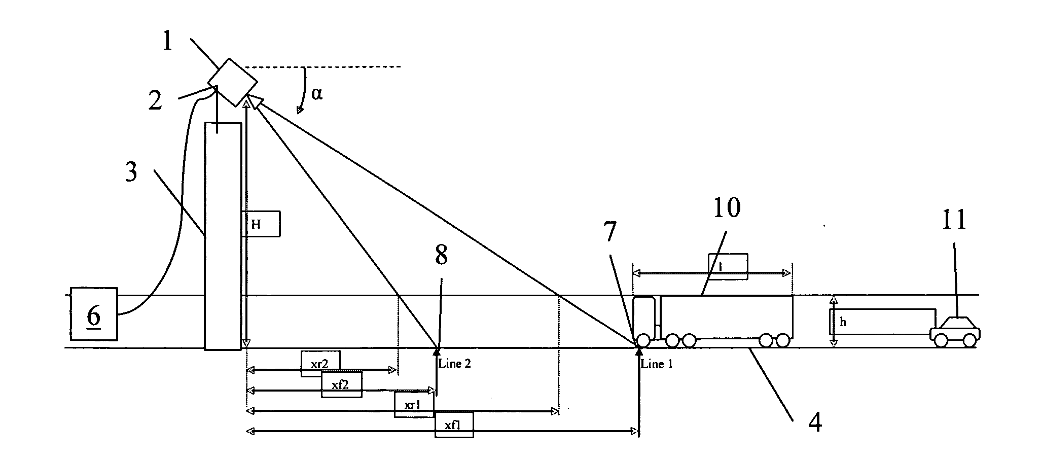
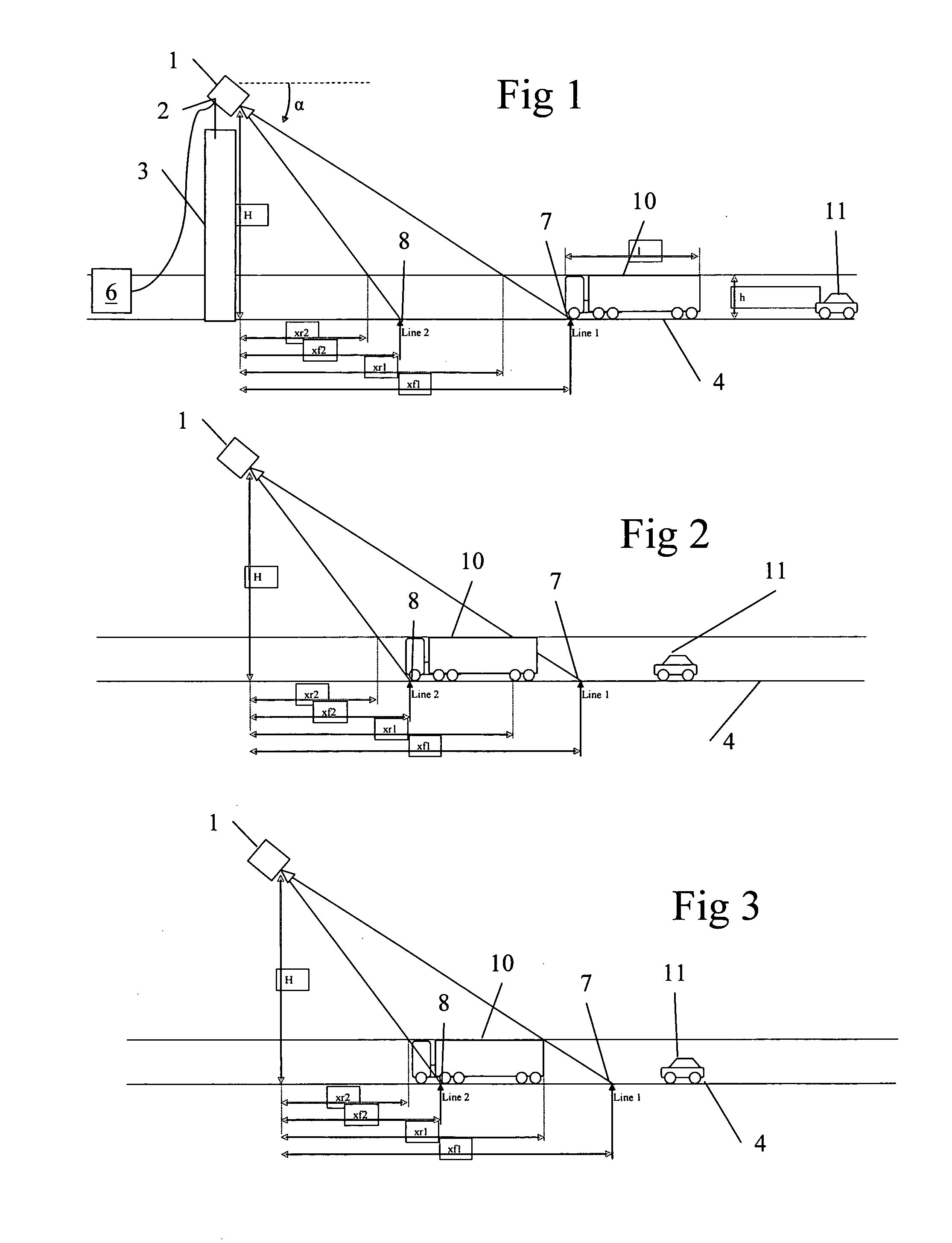
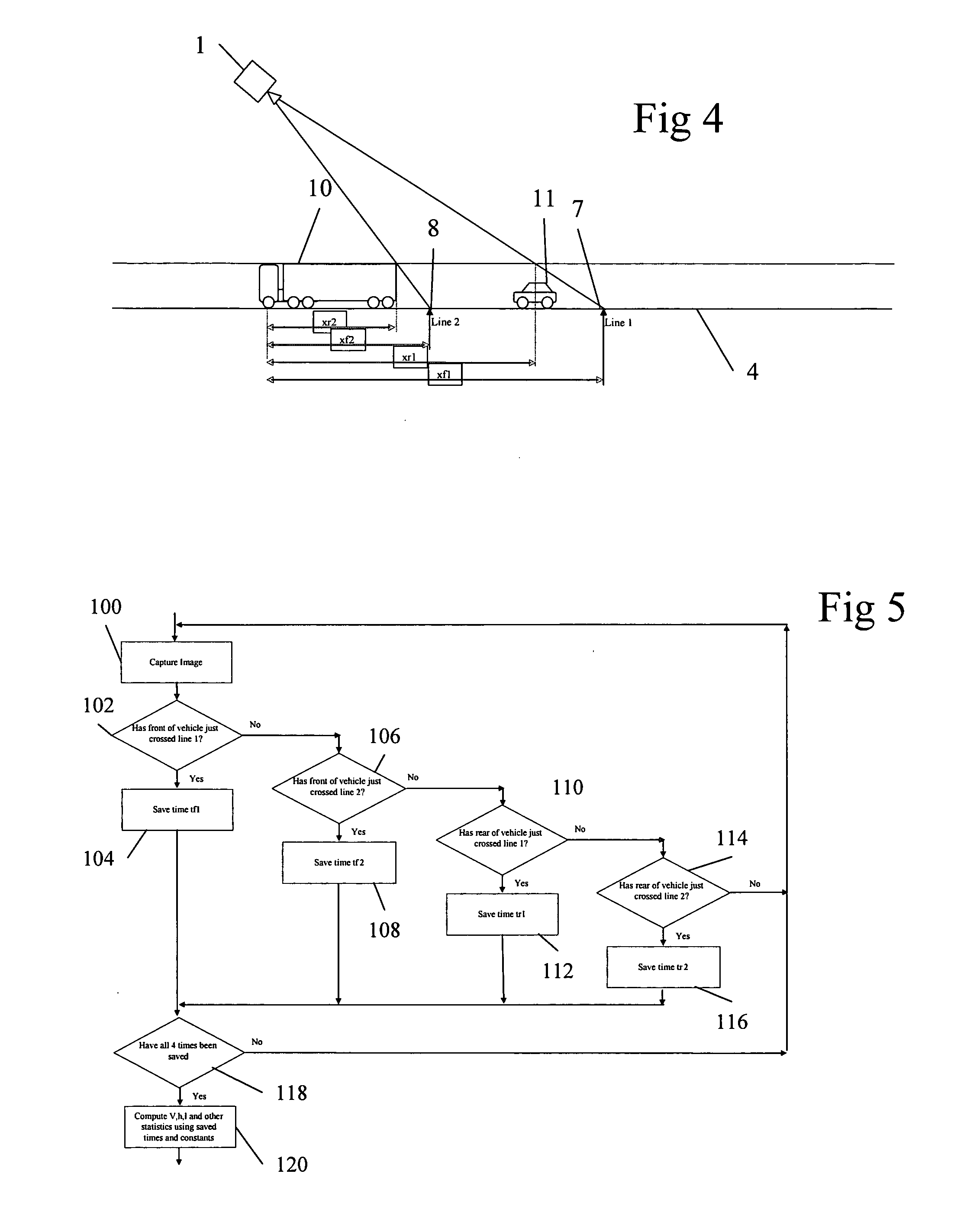
[0068]A traffic monitoring apparatus according to a first embodiment of the invention is shown in FIGS. 1 to 6 of the accompanying drawings. It comprises a camera 1 mounted on point 2 above a bridge or gantry depicted at 3. The camera is mounted so as to view a road 4 from its mounting point 2.

[0069]The camera is connected to a processing unit 6 which can be located distant from the camera 1. Alternatively, it can be located within the housing of the camera 1 or anywhere else convenient. Painted on the road surface are two lines—first line 7 and second line 8. The processing unit takes as an input images captured from camera 1. It analyses these images using techniques such edge analysis as discussed in WO02 / 092375 so as to determine when the lines are visible and when they are being blocked by the presence of vehicles on the road.

[0070]In an alternative embodiment, not directly depicted, the lines are not physically present on the surface of the road, but are each represented by an...


PUM


Abstract

A method of monitoring traffic on a road comprising capturing a plurality of images of the road using a camera mounted on a viewing point and associating a time of capture with each image, determining, from the captured images, the positions of the portions of the road surface visible from the viewpoint at the front and rear extremities of the extent of a vehicle in the captured images at two different times; and determining from the positions and the times of the instants at least one characteristic of the vehicle or its motion, such as the vehicle length, speed or a vehicle classification (truck, car, motorcycle, etc).

Description

CROSS-REFERENCE TO RELATED APPLICATIONS[0001]This application is a national stage of International Application No. PCT / GB2008 / 002969 filed Sep. 3, 2008, the disclosures of which are incorporated herein by reference, and which claimed priority to Great Britain Patent Application No. 0717233.1 filed Sep. 5, 2007, the disclosures of which are incorporated herein by reference.BACKGROUND OF THE INVENTION[0002]This invention relates to a method of and apparatus for traffic monitoring.[0003]Inductive loops have been used in vehicle detection since around 1960. At the present date, these systems have been used all around the world to determine vehicle presence, occupancy time and speed. Inductive loops are the most common means of acquiring traffic statistics.[0004]An inductive loop comprises a coil of wire embedded in a groove in the road surface. In order to perform this embedding, approval must be given by the road authorities and much manual work must be carried out in forming the hole ...

Claims


Application Information

Patent Timeline
Patent Type & Authority Applications(United States)
IPC IPC(8): H04N7/18
CPCG06K9/00785G06K9/3241G06K2209/23G06T7/20G08G1/0175G06T2207/10016G06T2207/30236G08G1/0104G08G1/015G06T7/60G06V20/54G06V10/255G06V2201/08
Inventor TUCKER, MARK RICHARDREEVE, JOHN MARTIN
Owner TRW LIMITED
Learn More