Rechargeable battery, anode, and current collector

a current collector and rechargeable battery technology, applied in the manufacture of electrodes, cell components, electrochemical generators, etc., can solve the problems of increasing power consumption and affecting the cycle characteristics of current collectors, and achieve the effects of improving cycle characteristics, increasing anchoring effects, and significantly improving adhesion of active anode material layers to current collectors

Active Publication Date: 2010-09-16
MURATA MFG CO LTD
View PDF6 Cites 19 Cited by
  • Summary
  • Abstract
  • Description
  • Claims
  • Application Information

AI Technical Summary

Benefits of technology

[0010]Along with recent, ever growing requirements for higher performance and expanded functionality of portable electric devices, the power consumption tends to increase in recent years, charge-discharge cycles of the rechargeable battery are repeated more frequently, and its cycle characteristics tend to degrade with more ease. Therefore, further improvements of the cycle characteristics of rechargeable battery are highly desirable.
[0013]With the current collector according to an embodiment of the invention, the current collector body included in the current collector is provided with the plurality of conductive particles disposed on the surface thereof, and the plurality of conductive particles includes the spherical particles and the plate-like particles. Since a tridimensional structure having complex shape (irregularities) is formed on the surface of the current collector body with the spherical particles and plate-like particles, anchoring effects are greatly increased. As a result, in the anode including the current collector of the invention, the adhesion of an active anode material layer to the anode current collector is considerably improved. Therefore, with the rechargeable battery including the abovementioned anode of the invention, cycle characteristics can be improved, since the deformation, damage, and so forth of the anode current collector are suppressed.

Problems solved by technology

Along with recent, ever growing requirements for higher performance and expanded functionality of portable electric devices, the power consumption tends to increase in recent years, charge-discharge cycles of the rechargeable battery are repeated more frequently, and its cycle characteristics tend to degrade with more ease.

Method used


Image

  • Rechargeable battery, anode, and current collector
  • Rechargeable battery, anode, and current collector
  • Rechargeable battery, anode, and current collector

Examples


examples

[0147]The following specific examples are provided further to illustrate preferred embodiments of the invention.

examples 1-1 and 1-2

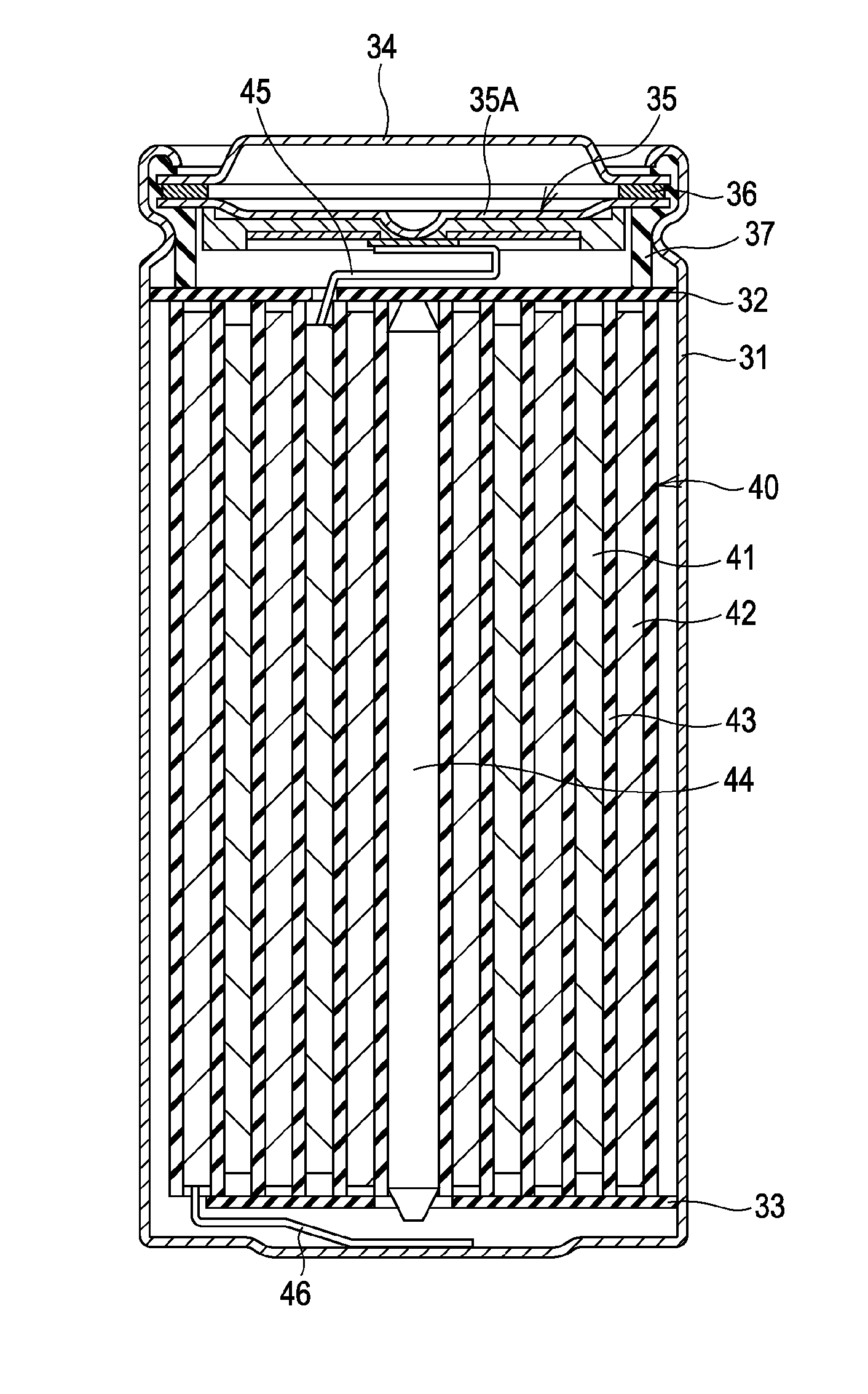
[0148]According to the following procedures, a coin-type rechargeable battery shown in FIG. 12 was produced. At this time, the rechargeable battery is devised to be a rechargeable lithium-ion battery which is configured such that the capacity of the anode is represented by the insertion and extraction of lithium ions as the electrode reaction substance.

[0149]In the first place, a cathode 71 was formed. More specifically, lithium carbonate (Li2CO3) and cobalt carbonate (CoCO3) were mixed at a molar ratio of 0.5:1, and this mixture was fired in air at 900° C. for 5 hours, whereby lithium cobalt complex oxide (LiCoO2) was formed. Thereafter, 96 parts by weight of lithium cobalt complex oxide (median size=5 μm) as an active cathode material, 1 part by weight of carbon black as a cathode conductive agent, and 3 parts by weight of polyvinylidene fluoride as a cathode binding agent were mixed to form a cathode mixture. Subsequently, the cathode mixture was dispersed into N-methyl-2-pyrroli...

examples 1-3 and 1-4

[0153]As shown in Table 1, the process steps proceeded in a manner similar to those described in the examples 1-1 and 1-2, with the exception that an electrolytic copper foil or rolled copper foil was used as-is for forming the anode current collector.

[0154]When the cycle characteristics were investigated for the rechargeable batteries of the examples 1-1 through 1-4, several results were obtained as shown in Table 1.

[0155]In the present investigation of the cycle characteristics, the cycle tests were carried out and discharge capacity retention ratios were obtained. Namely, after completing the first charge-discharge cycle in an atmosphere at 23° C. in order to stabilize the battery condition, another charge-discharge cycle was repeated and the discharge capacity value during the second cycle was measured. Subsequently, after completing 99 charge-discharge cycles in the same atmosphere, the discharge capacity value during the 101-th cycle was measured. Thereafter, the discharge cap...


PUM

PropertyMeasurementUnit
tensile strengthaaaaaaaaaa
diameteraaaaaaaaaa
mean particle sizeaaaaaaaaaa

Abstract

A rechargeable battery including a cathode and an anode each capable of inserting and extracting an electrode reaction material, and including an electrolyte, in which the anode includes an anode current collector which is formed by including a current collector body. The anode current collector is provided thereon with an active anode material layer, and a plurality of conductive particles disposed on the surface of the current collector body with the surface facing the active anode material layer. The plurality of conductive particles is formed to include spherical particles and plate-like particles. Since a tridimensional structure having irregularities is formed on the surface of the current collector body with the spherical particles and plate-like particles, anchoring effects are greatly increased. As a result, the adhesion of the active anode material layer to the anode current collector is considerably improved.

Description

BACKGROUND OF THE INVENTION[0001]1. Field of the Invention[0002]The invention relates generally to current collectors, anodes, and rechargeable batteries. More particularly, the invention provides a current collector for use in electrochemical devices, and an anode and a rechargeable battery each including the current collector.[0003]2. Description of the Related Art[0004]With the recent trend of widespread use of portable electric devices such as video camera, digital still camera, cellular phone, notebook computer, and so forth, the miniaturization, weight reduction, and extended life, of these devices have been eagerly desired. In order to meet the demands for electronics applications, the development of batteries, and of rechargeable batteries, in particular, has been actively pursued as to satisfactory power sources that are feasible of achieving the miniaturization, lighter-weight, and higher energy density.[0005]Among others, rechargeable lithium-ion batteries, which utilize ...

Claims


Application Information

Patent Timeline
Patent Type & Authority Applications(United States)
IPC IPC(8): H01M4/02H01M4/134H01M4/1395H01M4/66H01M4/70
CPCH01M4/0421H01M4/134H01M4/661Y02E60/122H01M4/667H01M4/70H01M10/0525H01M4/664Y02E60/10
Inventor IWAMA, MASAYUKIKAWASE, KENICHIHIROSE, TAKAKAZU
Owner MURATA MFG CO LTD
Why Eureka
Try Eureka