Apparatus and method for integrated vessel ligator and transector

a technology of integrated vessel and ligator, which is applied in the field of tissue transectors, can solve the problems of inability to properly operate the scissor blade, block the thorough electrocauterization of the side branch vessel, and other impediments to orderly surgical procedures, and achieve the effect of facilitating the transecting of tissu

Inactive Publication Date: 2010-09-16
MAQUET CARDIOVASCULAR LLC
View PDF101 Cites 13 Cited by
  • Summary
  • Abstract
  • Description
  • Claims
  • Application Information

AI Technical Summary

Problems solved by technology

However, placement of the electrodes in relation to the tissue-shearing edges of the scissor blades may inhibit proper operation of the scissor blades to shear tissue and may inhibit thorough electrocauterization of a side branch vessel as the scissor blades close during transection of the vessel.
The associated linkage to a manual actuator at the proximal end of the elongated body commonly establishes little mechanical advantage sufficient for remotely shearing tissue under control of the proximal actuator, with resultant jamming of the scissor blades or other impediments to orderly surgical procedures.
Additionally, repeated opening and closing of the scissor blades is a tedious procedure required to slice tissue along an extended path.
However, visualization through the transparent tip of the tissue being dissected is commonly obscured by tissue and bodily fluids that contact the tip.
In addition, insufflating an anatomical space via gas introduced under pressure through the access port becomes more problematic as the anatomical space is extended remotely from the access port and the dissected tissue surrounds the dissecting instrument.

Method used


Image

  • Apparatus and method for integrated vessel ligator and transector
  • Apparatus and method for integrated vessel ligator and transector
  • Apparatus and method for integrated vessel ligator and transector

Examples


Embodiment Construction

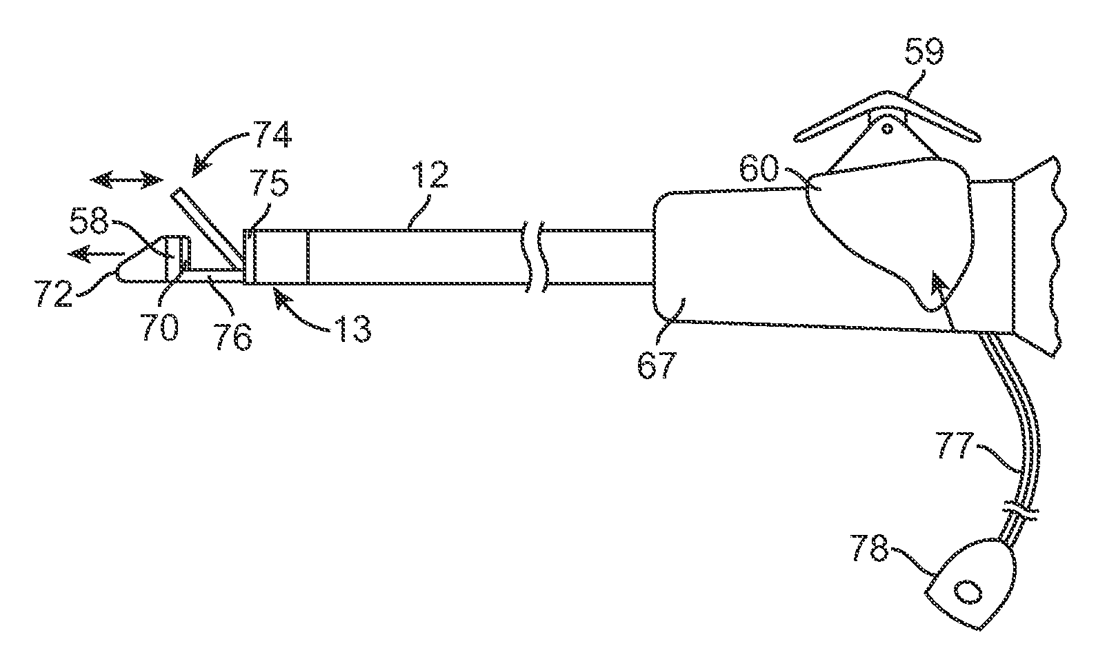
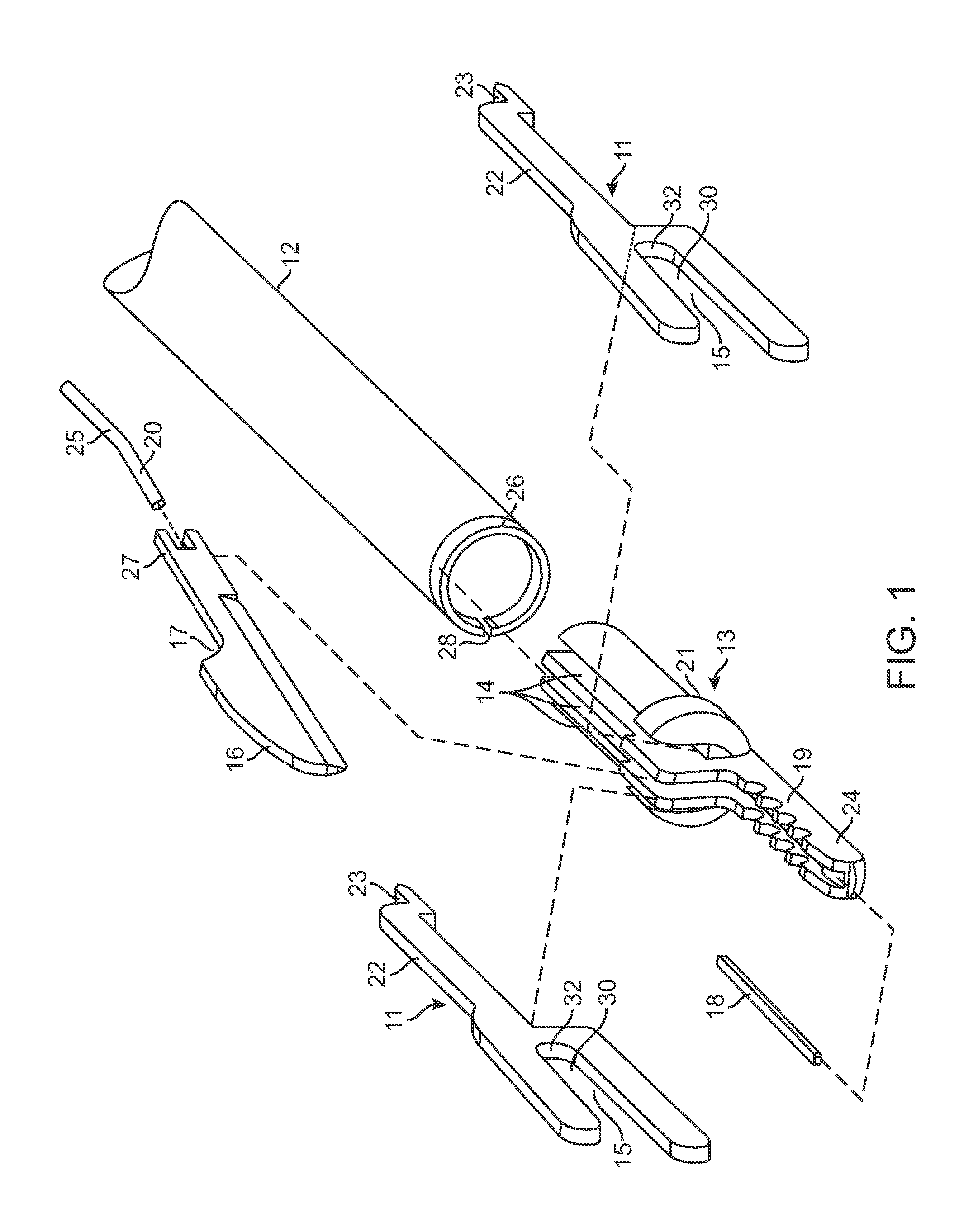
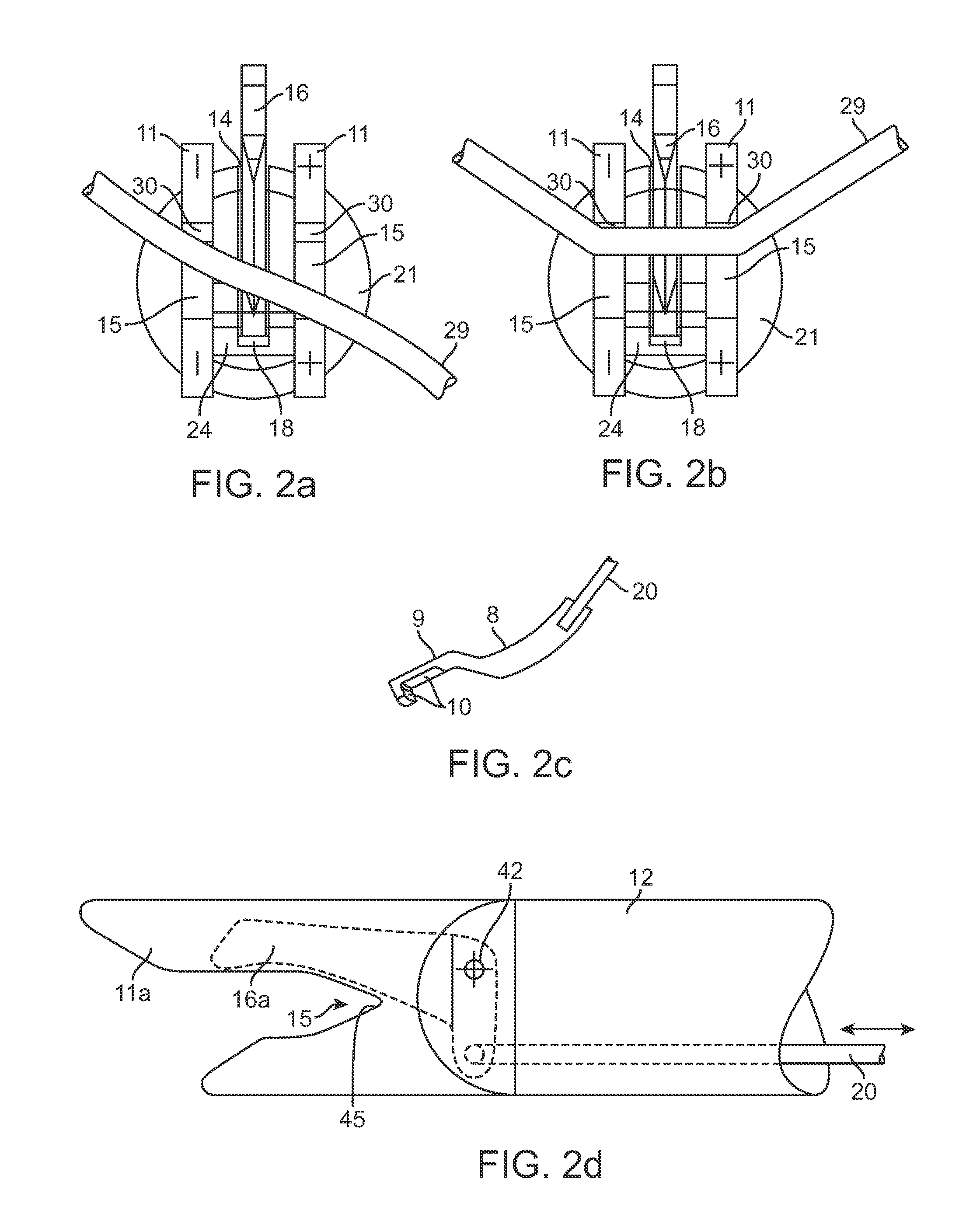
[0026]Referring now to the exploded perspective view of FIG. 1, there is shown the distal end of an elongated hollow support body 12 for the tissue electrocauterizer and transector in accordance with one embodiment of an end effector of the present invention. An electrically-insulating hub 13 formed of a polymer such as polycarbonate is disposed to fit within the internal bore of the body 12, up to the axial extent of a flange 21 surrounding the perimeter of the hub 13 at about the mid-length thereof. The hub 13 includes three spaced, parallel slots 14 that are vertically aligned to receive therein a tissue-slicing blade 16 in the central slot and two yoke-shaped planar electrodes 11 in the slots 14 disposed on opposite sides of the central slot. Each of the electrodes 11 includes an axially-aligned recess or slot 15 having a width that may taper inwardly 30 from a forward edge of the electrode, as shown in FIGS. 2a, 2b, or that may be substantially uniform in width along the length...


PUM


Abstract

Surgical treatment of tissue includes electrocauterization of blood vessels interposed between spaced sets of electrodes of opposite polarity, and includes transection of such tissue by a cutter that is mounted between the spaced sets of electrodes for translational and lateral movement relative to the sets of electrodes. Orientations of the sets of electrodes within a range of angles about an elongated axis of a supporting body are controlled by manual movement of an actuator mounted near a proximal end of the body for movement through a smaller range of angles via linkage connecting the actuator to the electrodes. Tissue dissection with gas insufflation to form an anatomical space in tissue is facilitated by a fluid outlet port located near the tissue-dissecting tip at the distal end of the elongated body that delivers through the tissue-dissecting tip to the dissected tissue a fluid under pressure that is supplied along a lumen within the elongated body.

Description

RELATED APPLICATIONS [0001]This application is a continuation-in-part of application Ser. No. 10 / 455,942 entitled “Dissection and Welding of Tissue”, filed on Jun. 6, 2003 by Albert K. Chin, et al., which is a continuation-in-part of application Ser. No. 10 / 054,477 entitled “Vessel Harvesting Apparatus And Method”, filed on Jan. 18, 2002 by M. Stewart, et al., which is a continuation-in-part of application Ser. No. 09 / 413,012 entitled “Tissue Dissector Apparatus and Method”, filed on Oct. 5, 1999 by Albert K. Chin, which is a continuation of application Ser. No. 09 / 133,136 entitled “Tissue Dissector Apparatus And Method”, filed on Aug. 12, 1998 by Albert K. Chin.FIELD OF THE INVENTION [0002]This invention relates to tissue transectors, and more particularly to such devices having electrocautery electrodes disposed for selective cauterization and captivating of tissue structures such as blood vessels during surgical procedures to hemostatically seal and transect the vessels.BACKGROUN...

Claims


Application Information

Patent Timeline
Patent Type & Authority Applications(United States)
IPC IPC(8): A61B18/14A61B17/32
CPCA61B17/00008A61B2018/1455A61B17/320016A61B18/1442A61B18/1445A61B18/28A61B2017/00212A61B2017/00504A61B2017/00973A61B2017/320044A61B2018/00345A61B2018/00404A61B2018/00601A61B2018/00619A61B2018/00916A61B2018/00982A61B2018/1407A61B2018/1412A61B17/0218
Inventor STEWART, MICHAEL C.WILLIS, GEOFFREY H.LAMBERTI, JOSEPH N.ADAM, CHARLES J.INO, HARRYLUNSFORD, JOHN P.
Owner MAQUET CARDIOVASCULAR LLC
Why Eureka
Try Eureka