System and method for controlling rate-adaptive pacing based on a cardiac force-frequency relation detected by an implantable medical device

a technology of force-frequency relation and rate-adaptive pacing, which is applied in the direction of suction devices, catheters, therapy, etc., can solve the problems of inappropriate rate-adaptive pacing, increase contractility dysfunction, and decrease the slope and/or abscissa. , the effect of decreasing the slope and/or abscissa

Inactive Publication Date: 2010-09-16
PACESETTER INC
View PDF33 Cites 343 Cited by
  • Summary
  • Abstract
  • Description
  • Claims
  • Application Information

AI Technical Summary

Benefits of technology

[0014]Additionally, a significant decrease in the slope and / or abscissa of the force-frequency relationship (relative to baseline values) can be associated with increasing contractility dysfunction and with heart failure progression. Warning signals can be generated accordingly. Again, suitable thresholds can be used. Diagnostic data is preferably recorded indicative of the force-frequency relationship. If the implanted device is equipped with a drug pump, suitable medications can be automatically administered (or their dosages titrated) in response to a significant decrease in force-frequency slope and / or abscissa. In one example, verapamil is delivered to the patient to reduce ventricular-vascular stiffening so as to increase contractile force.

Problems solved by technology

Within patients with contractility dysfunction, rate-adaptive pacing may be inappropriate.

Method used


Image

  • System and method for controlling rate-adaptive pacing based on a cardiac force-frequency relation detected by an implantable medical device
  • System and method for controlling rate-adaptive pacing based on a cardiac force-frequency relation detected by an implantable medical device
  • System and method for controlling rate-adaptive pacing based on a cardiac force-frequency relation detected by an implantable medical device

Examples


Embodiment Construction

[0026]The following description includes the best mode presently contemplated for practicing the invention. This description is not to be taken in a limiting sense but is made merely to describe general principles of the invention. The scope of the invention should be ascertained with reference to the issued claims. In the description of the invention that follows, like numerals or reference designators will be used to refer to like parts or elements throughout.

Overview of Implantable System

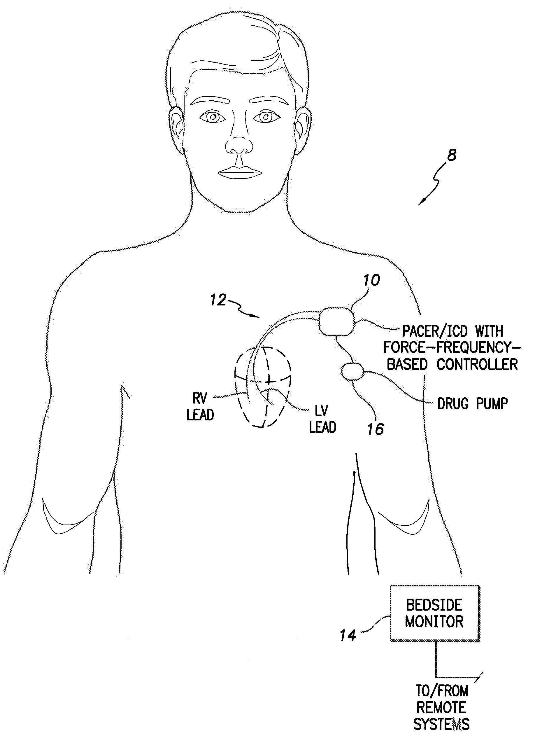
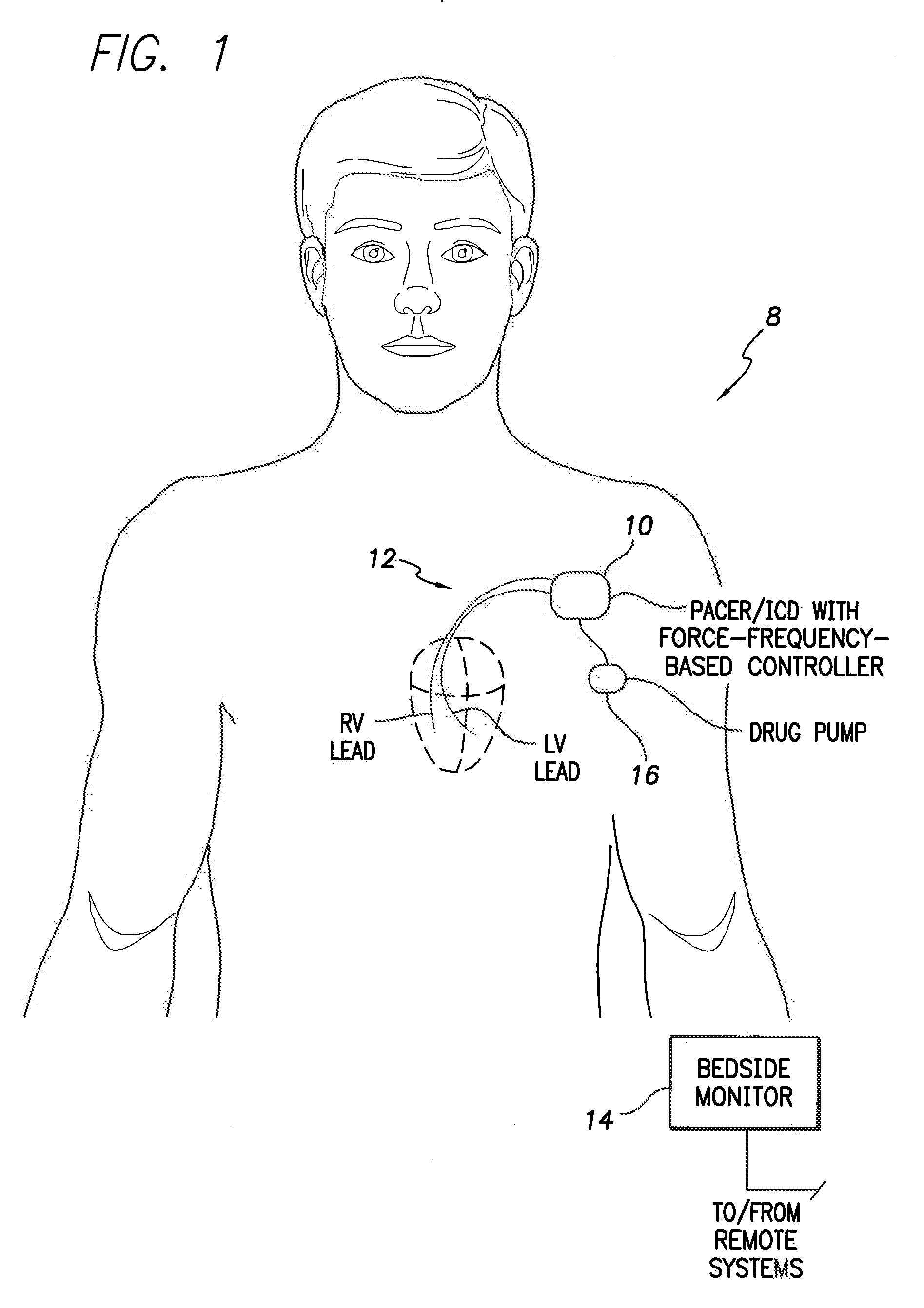
[0027]FIG. 1 illustrates an implantable medical system 8 capable of determining, monitoring and exploiting the force-frequency relationship within the heart of a patient and, in particular, for controlling rate-adaptive pacing based on the force-frequency relationship. To this end, medical system 8 includes a pacer / ICD 10 or other cardiac rhythm management device capable of detecting one or more parameters representative of myocardial contractile force via cardiac sensing / pacing leads 12 implante...


PUM


Abstract

Techniques are provided for use in controlling rate-adaptive pacing within implantable medical devices such as pacemakers or implantable cardioverter-defibrillators (ICDs). In one example, a force-frequency relationship is determined for the heart of the patient, which is representative of the relationship between cardiac stimulation frequency and myocardial contractile force. To this end, various parameters are detected for use as surrogates for contractile force, including selected systolic pressure parameters and cardiogenic impedance parameters. Rate-adaptive pacing is then controlled based on the detected force-frequency relationship to, for example, deactivate rate-adaptive pacing if the slope and/or abscissa of the force-frequency relationship indicates significant contractility dysfunction within the patient. In other examples, rather than deactivating rate-adaptive pacing, control parameters are adjusted to render the rate-adaptive pacing less aggressive. In still other examples, trends in the slope and/or abscissa of the force-frequency relationship are monitored to detect contractility dysfunction and/or heart failure and titrate medications accordingly.

Description

FIELD OF THE INVENTION[0001]The invention generally relates to implantable medical devices, such as pacemakers or implantable cardioverter-defibrillators (ICDs), and in particular to techniques for controlling rate-adaptive pacing within patients in which such devices are implanted.BACKGROUND OF THE INVENTION[0002]A pacemaker is an implantable medical device that recognizes various arrhythmias such as an abnormally and delivers electrical pacing pulses to the heart in an effort to remedy the arrhythmias. An ICD is an implantable device that additionally or alternatively recognizes ventricular tachycardia (VT) and / or ventricular fibrillation (VF) and delivers electrical shocks or other therapies to terminate these tachyarrhythmias.[0003]Many state-of-the-art pacemakers and ICDs are equipped to perform rate-adaptive pacing. With rate-adaptive pacing (sometimes also referred to as rate-responsive pacing or rate-variable pacing), the device automatically changes the rate at which pacing...

Claims


Application Information

Patent Timeline
Patent Type & Authority Applications(United States)
IPC IPC(8): A61N1/365A61M1/00
CPCA61B5/1459A61N1/3627A61N1/36585A61N1/36564A61N1/36521
Inventor KOH, STEVE
Owner PACESETTER INC
Why Eureka
Try Eureka